|
Before we start, remember
that almost every motorized component is a compromise to some extent.
Adding an intercooler to your super/turbocharged engine costs power &
throttle response whilst in vacuum & very low boost!
Fit an intercooIer to a naturally aspirated engine & see what it does to
the power output curve. For a couple of decades when nearly all
competition & modified street engines in Australia were naturally
aspirated, opening up the ports or at least matching them with the
intake manifold was almost mandatory. So we worried about a small
mismatch of usually no more than 0.5mm. then, but some people now buy a
great monstrous chunk of alloy that tortures the same intake charge (&
isn't cheap) without much thought at all ! An intercooler causes a
static pressure drop across the core because of the extra
resistance of the Intake charge "rubbing" on the internal walls of the
"tube" & cooling "fins/ribs" create. This can vary between
approximately 0.3 to 5.0 psi. static pressure drop. The trick is too
cool the intake charge the most, with the least static pressure drop.
The more temperature that is pulled out of the intake charge, the higher
the dynamic pressure drop has to be, because the cooler air is denser &
occupies less volume. Simple physics. To judge a core properly on
pressure drop, you have to know the static pressure drop & subtract it
from the dynamic pressure drop, with the higher resulting figure
indicating a more efficient core - the exact opposite to what you may
first think. The denser the air, the more oxygen ( there is approx. 22 %
oxygen in the atmosphere, & it is only oxygen that will burn in the
combustion mixture), the more kw. produced. A rough rule of thumb is for
every 10° farenheight - 1% extra kw. is produced ! So even though it
does theoretically cost power with pressure drop,
the denser intake charge easily compensates for this,
with a power gain between not much to a bloody lot, realized !! The more
the charging device beats & heats up the intake charge, the higher the
power gains from intercooling & more importantly to me, the safer
(engine component life) the gains are made. No point in winning the race
back to the mechanic for a new headgasket , or worse, a new set of
pistons, each time.
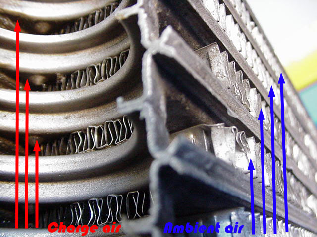
The heat from the intake
charge is dissipated by contact with the surface of the interior walls
(fins or extrusions), and then it transfers through the thickness of the
"tube" wall to the surface of the exterior fin, from where it is
transported away by the passing ambient air flowing through the core.
It seems that due to the cost of new fabricated intercoolers, a lot of
people are looking for a cheap alternative. However, as the old
saying goes, 'you only get what you pay for' and usually the same
applies to intercoolers. There are significant differences in
intercoolers, not only in core construction (bar and plate or tube and
fin etc.), but also their design (especially end tank design).
There is usually a reason
for the cost involved in buying a new intercooler (whether it be ARE or
another company), and they do offer advantages over other options,
especially cut down truck intercoolers
ENGINE DESTRUCTION ! ! ! !
The most single deadly
forced induction engine destroyer (apart from no oil) has two common
names :- Detonation or when I did my time at college,
Pre Ignition. My interpretation of these is when the spark plug
ignites the intake charge, the flame front travels rapidly but smoothly,
across the piston face to fill the combustion chamber with the exploding
fuel charge & force the piston back down the bore. When something
happens to destabilize the smooth travel of the flame front (wrong
combustion chamber/piston dome shape, little/no squelch surface, sharp
edges, hot heat range plugs, advanced timing, excessive compression,
high boost, too low octane fuel,) one or more smaller fronts can start &
these then collide, resulting in an early &/or more violent explosion,
resulting in the knocking or pinging noise that sometimes can be heard
from the top part of the engine. Interestingly, it is easier to hear a
standard car/ute ( our terrible unleaded) pulling away from the lights
up a hill, than it is a turbocharged car. I have to admit that I lost an
engine of mine only this year, whilst testing on the open road
(steepish hill) without hearing it. Radio on low & passenger reading
data, I felt the engine nose over but by the time I clicked it & coasted
to a stop, it was missing on one cylinder - side gone out of the top of
the piston - expensive! That quick. Don't pass me off as a dickhead & it
wont happen to you, be aware. The boost gauge decided to read at 60% of
actual boost sometime just before the testing started, I adjusted it up
thinking someone had changed it & it's that simple.
The cooler the intake charge - the less chance you have of detonation !
I'm also positive that a consistently stable (air/water is supreme here)
cooler intake charge also increases the life of headgasket, valve &
seats, top bore-ring-ring land to a noticeable degree, whilst offering
considerable more power potential. How important is intercooler
selection now ????
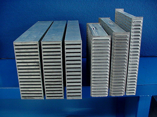
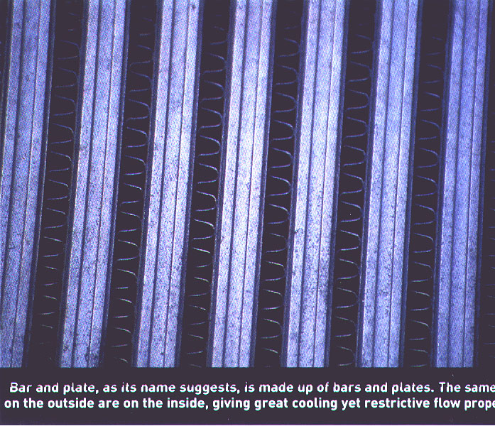
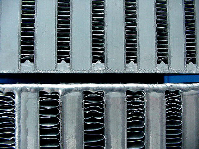
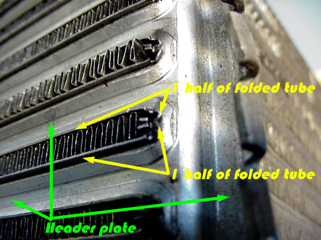
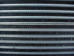
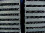
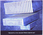
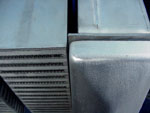
Bar and Plate, Extruded Tube and Fin, Folded Tube & Fin or
Plate tube & fin?
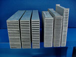
115, 90, 75mm bar/plate on left & 73, 57, 3mm
tube/fin on right. |

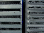
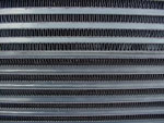
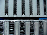
Close up of bar/plate (heavy) on the
left & tube/fin (tough) on the right |
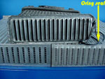
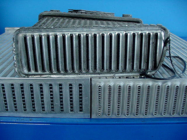
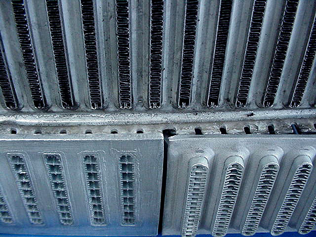
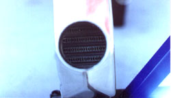
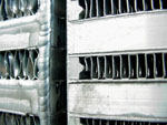
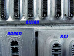
Nissan folded tube & fin on top. Adrad on left
& K&J on right bot. - both are extruded tube - tough. |
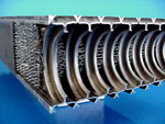
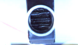
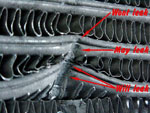
Denso plate tube & fin. Too many seams + too
weak. Usually small thinner tubes with close fine fins. |
|
The intercooler cores
produced by both manufacturers in Australia are extruded tube & fin
design. There are actually 4 manufacturers of aluminium radiator cores
in Australia - ADRAD in Adelaide, DENSO in Melbourne, K&J in Currumbin &
NATRA in Melbourne - but only two of these will make a core to size
(npn) & it also happens that the same two are the only ones too
manufacture intercooler cores - ADRAD and K&J ! A variant of the
extruded tube core is the folded tube core, which has two thinner wall
sections with a seam folded to the inside, manufactured by Calsonic in
Japan & fitted oe by Nissan - including the GTR. Bar & plate is most
common in the USA. aftermarket (& strong in trucking industry), whilst
the plate tube is common in oe. intercoolers in Japan - mostly Denso -
Toyota & Diahatsu, & a couple of Mazda models. Japans aftermarket
is more tube & fin than bar & plate when looking through the catalogues,
with no aftermarket performance plate tube & fin cores from any country
- thank goodness.
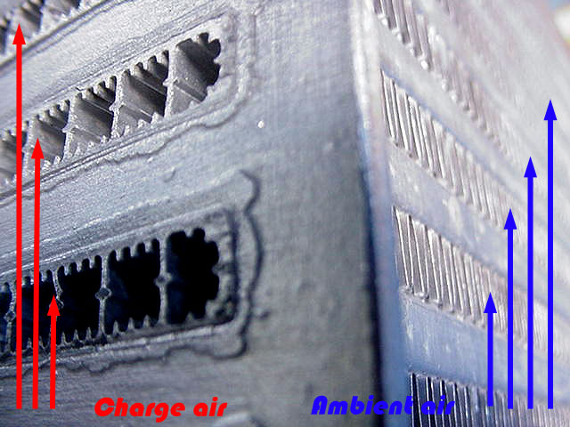
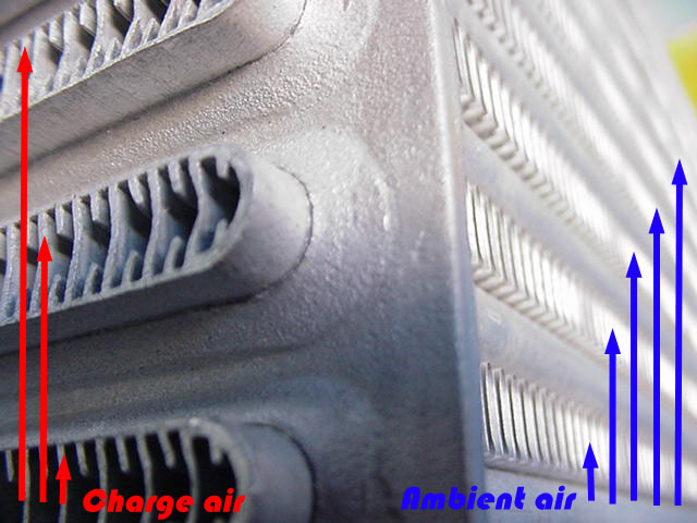
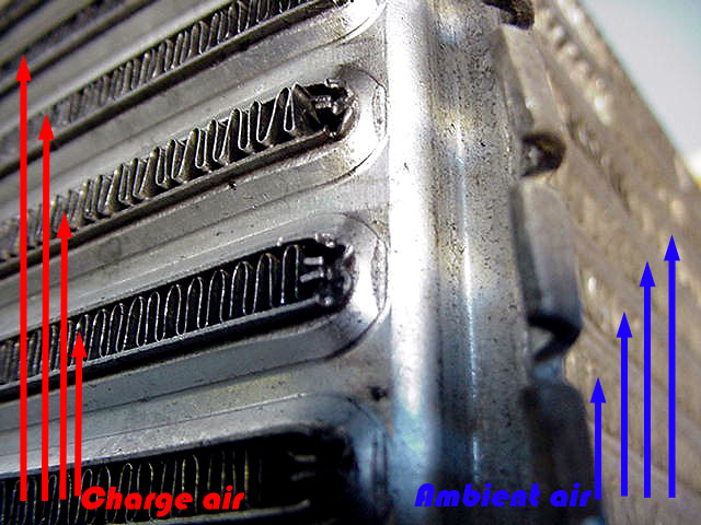
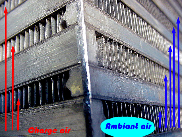
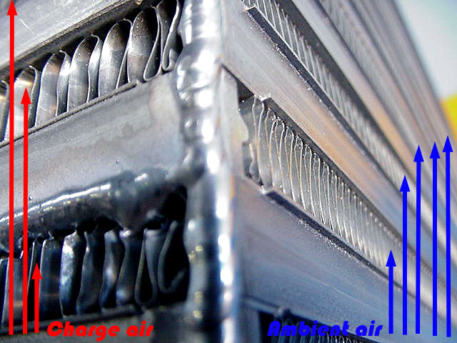
AIR FLOW.
The above pictures show how in all the different
intercooler design/production methods, one basic feature is common
to all - the Ambient air flow is at ninety degrees to the Charge air
flow.
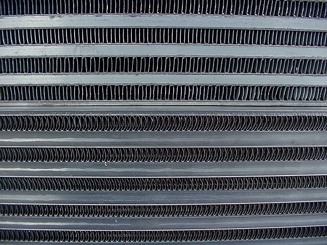
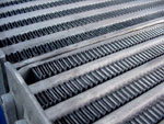
AMBIENT AIR FLOW
Tube/fin top core & bar/plate underneath.
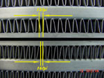
These are average fin pitches, but if needed, we vary them to
suit the purpose. |
Our bar/plate top & Garrett below. Ours does
not have as close fpi & being neat, allow more air through to
the radiator |

May 2002 HOT4's - tiny tubes with large
ambient fins like this should only be for an air water
application |

May2002 Hot4's -super wide fin spacing like
this could only be for extreme high cfm @ low temperature,
or cheap ! |

Adrad tube. Ambient air brakes off back of
tube good.
|

Denso tube. Air brakes off back of tube good.
|

Garrett tube. Air brakes off back of tube
okay.
|

K&J tube. Air brakes off the back with highest
drag, negating the benefit of best entry performance
|
Tube & fin cores penetrate
the ambient air (channel the cooling air) better - less disturbance -
than plate tube & fin cores which penetrate just better than bar & plate
cores. Remember that in front mount applications, this has a small
effect on the engine water temperature, by slowing the air speed &
volume, before it reaches the radiator. This is because the rounded
leading edge of the extruded tube parts the air with less turbulence
than the "W" shape of the plate tube & fin core, only because this core
has thinner tubes than the other two. If the square leading edge of the
bar & plate tube was as thin as the plate tube, then it would flow
better, but it comes a close third. The above drawings illustrate the
turbulence caused by the three tube shapes. Please note that with the
leading edge of intercooler tube shape, we are talking very small
differences between them with tube pitch (spacing) having more effect
than tube shape on ambient air flow, and it has little effect on charge
heat dissipation, actually having allot more of an effect on radiator
cooling efficiency.
One point often overlooked is the body work across the front of the
vehicle. Modern car designs have evolved to aerodynamic swoopy
nosecones, which look great & give low drag coefficients, but make
intercooling & efficient engine system cooling, much more a science than
a few years ago. Most of the current designs rely on a low scoop just in
front of the radiator for the majority of air flow, so this has to be
taken into account when mounting the intercooler. The less direct path
the ambient air travels to the intercooler, the slower it's speed & so
it's ability to force it's way through the core, resulting in both core
thickness & fin pitch choice being much more important. Surface
area should be increased to compensate when core thickness &/or fin
pitch are reduced & ducting fabricated to channel all air possible to
the core & then through the radiator. . The same goes for Cars/four
wheel drives that have driving lights, winch etc. mounted in front of
the grille.
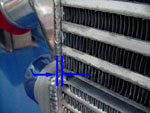
CHARGE AIR FLOW
Below is what the intake charge see's.
Tube/fin core Picture - Driftking |
bar/plate core Picture - driftking |
Much more important (to performance) than the ambient air flow
disruption is the charge air flow disruption entering the core flow
passages. Least effected (as manufactured) is air entering the plate
tube & fin core as the plates are stamped with a small radius as part of
their construction & the fact these tubes are always allot narrower,
however, check the paragraph on tanks before getting too excited.
Bar & plate cores are next, as the top surface is flat with a sharp 90
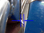
deg. edge. Tube & fin cores (both types) are definitely the worst as the
tubes are proud of the header plate causing some of the charge air
to do a 180 deg. turn at the plate then another 180 deg. turn to enter
the tube. Allot of turbulence/drag/static pressure drop! Most
manufacturers of these cores take the safe/fast way in production & cut
the tube lengths longer than necessary, hurting air flow, but knowing
that the product is integrally sound. The tubes usually stick up around
3-4mm, which makes the air flow do 2 distinct 180 deg, turns. The cores
out of the new Adrad factory are no more than 1mm proud of the header
plate, so they have really tightened up there production tolerances.
ARE. has a "venturie plate" option that gives the air flow a proper
radiused entry into the tube, increasing air flow by approx. 8.4%. @
10psi., an extremely worthwhile gain,& the only manufacturer I know of
doing this ! Once again Lateral thinking & R&D gives our customers an
advantage.
To size an intercooler properly, the most important
factor is what I call " the charge air window". This is the
surface area of the tubes for the charge air to enter. With cores from
the same manufacturer, just multiply the core height by the thickness,
but too compare cores from different manufacturers properly, you must
work out the surface area of each tube (allowing for fin/ribs etc.) &
count how many tubes in each core. The window controls two parameters, -
the pressure drop of the air entering the tube, so if he window is too
small for the cfm flow, the pressure drop increases. Most importantly,
if the window is too small, the air speed through the core will be too
high & not allow enough time for the heat to dissipate out of the
charge. If you play it safe & go too big in the widow size, then the
tube length needs to be kept short, or pressure
drop increases for little extra cooling. Best way
is too size the intake window for the cfm. requirement, then the length
of the tube for the heat dissipation requirement. That is for the same
kw. output, a larger turbo needs a larger window & a smaller turbo needs
a longer tube - generally.
COOLING CAPACITIES
(following some very
contentious paragraphs)
As a general rule, with a level playing
field (manufacturing quality, both fpi's, tube size, thickness, & a
hundred other variables), bar & plate intercooler cores dissipate more
BTU's than plate tube & fin & then tube & fin cores - per square
centimetre. Please stop, go back & read that sentence again, as it
is the most often asked question, but the most misquoted answer of all
time. Please also note that it is very easy to change just one
specification of a core to make it better than the other (forget plate
tube & fin here), & it must be remembered right now that heat
dissipation is only one parameter of overall intercooler performance. If
there is enough area & volume available, I mostly recommend a tube & fin
core to do the job, as it will get the temperature down close to bar &
plate, but at less pressure drop & less chance of leakage.
The most consistent method of charge air
heat transference is Extruded tube. This is because the aluminium is
forced through the extrusion die during manufacture, giving a 100%
wall to rib bond as there is no join in the material. The next most
consistent is the "square" shaped fin, as it is stamped with a flat
surface to fuse onto the tube wall, giving up too 10 times the surface
area to bond to the tube over the least consistent, folded fin, which is
the most common in bar & plate, & all that's seen in plate & fin cores.
We have seen intercoolers where the tolerance of the fin fold width is
too narrow & so the fin didn't fuse too the tube wall, resulting in no
heat transference in that area. Also the fins can bunch up, leaving a
gap either side, very inefficient. Another reason for the difference in
the price of cores - quality control against sloppy manufacture.
The most efficient method of Charge air
heat entrapment is folded fin, because louvered fin configurations &/or
very close fin per inch ratios can be utilized, resulting in higher
surface areas to "grab" the heat. Note that these also cause the
greatest pressure drop. It really comes down to manufacturing quality &
specifications between folded fin & extruded tube efficiency as they can
give similar results. Some folded fins have holes to break up the air
flow, some have louvered fins to channel the air & some are plain flat,
but they usually have higher fpi. ratios. Extruded tube dividing walls
are either flat or have ridges running length ways for increased surface
area.
Below are 5 pics of different bar/plate cores. You have to know all the
specifications to be able to accurately judge which core suits your
application best, Then there's tube/fin !!
Our 3rd. generation bar/plate on
left compared to best the same factory offered on right. Big
difference in performance. Both a larger tube & more fins = cool |
Top is narrower charge passage to
ambient ratio compared to bottom. Note bloody sloppy quality of
bottom core! We have to straighten fins before welding
tanks on. |
On the left is a louvered fin
(more cooling & pressure drop) & on the right is punched
fin. Different results. |
May 92 HOT4's shows ridicules course finning I
can't think of any application for this except cost. Not even
air/water. |
May 02 HOT4's shows three
examples of course finning which is inefficient, cheap, &
flooding our market. Be wary ! ******CHEAP
can mean
HEAT******* |

Three different bar/plate core from 2
different manufactures. Note the very small "tube" size for
water cooling in the air/water core. Also the courser fpi. of
the Spearco air/air core
|
There are some cases where I will
definitely not recommend a tube & fin core & they are where there is not
enough room for a properly sized core, usually upgrades in the oe.
position - Subaru top mounts, S13,14,15, Skyline GTS, 300ZX inner guard
etc. or big kw. applications. The thickest tube & fin core made in
Australia is 75mm & there are allot of applications where that will not
allow large enough intake window area size, causing a pressure buildup
in the inlet tank with the charge trying to get into the tubes & too
high air speed through the tubes, to be able to pull the heat out of the
charge. Note: This has now changed as of August 2002 with ADRAD
producing 109mm & 146mm thick tube/fin, & having instigated & played a
part in their development, I mostly recommend these cores except for
extreme cfm & heat applications ie: very large turbo's working near or
above their efficiency range, size not available or not enough room -
header plate size. It is impossible to repair a leak near the centre of
a thick core, & because tube/fin is both stronger & less prone to leaks,
they get my vote. I have not made any mention of the plate tube & fin
core, because to my knowledge, the Japanese plants only supply to the
oe. industry & do not sell to the aftermarket. For overseas customers, I
have seen thicker tube & fin cores made in Japan & I imagine these could
be a viable alternative.
An advantage of the bar & plate core
is when there is a lack of room situation in thickness at the tank ends,
as a tube & fin core has to have the outside of the tank at least 6mm
proud of the tubes on each side (absolute min. 87mm tank on a 75mm
core), whereas the tank can be a few mm inboard of the bar & plate core
86mm tank on a 90mm core). This can be very important in cars with short
engine bay/grille areas (Datsun 1600, Hi Lux etc.).
Note that usually, the more surface area,
the higher heat transference, but also the greater pressure drop. There
is no across the board, standout performer in the above three cores, as
they all have there strength & weaknesses, but it is a two horse race,
as plate & fin cores are only available oe., meaning smaller sizes for
lower kw. applications. They have too much static pressure drop & are
too weak to be manufactured in large sizes. You will have to add you own
interpretation to what the company you are dealing with has to say, &
hope they know exactly what they are talking about
Plate tube & fin tanks, for
charge air flow, are a basic disaster with the high capillary turbulence
caused by the approx. 240 deg. convoluted walls causing a large static
pressure drop. I have never bothered to measure the flow drop because
there is no point - only used in oe applications, thank goodness. Sorry
Denso, but that design is a shocker, it should be left to oil coolers,
if at all ! These must have been designed by accountants.
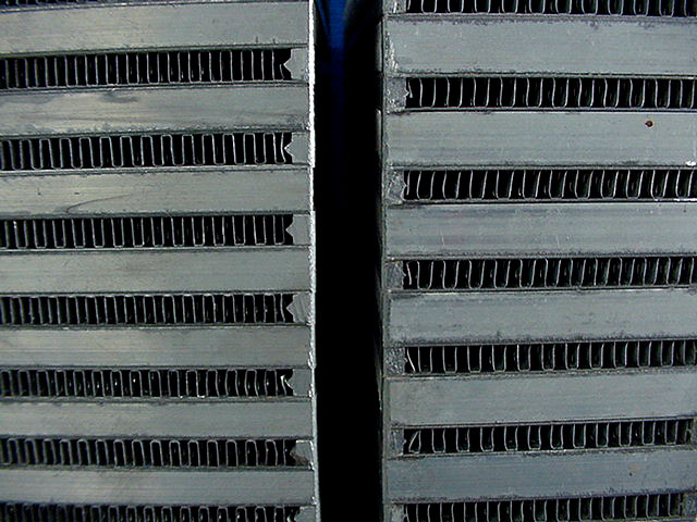
Core Construction
|
115, 90 & 75mm bar/plate on left. 73,57,37mm
tube/fin in right.
|
Our bar/plate on the left & K&J tube fin on the
right.
|

Nissan skyline oe on top. Adrad on left & K&J
tube/fins on right.
|
|
Real close up of the three different header
plate designs.
|
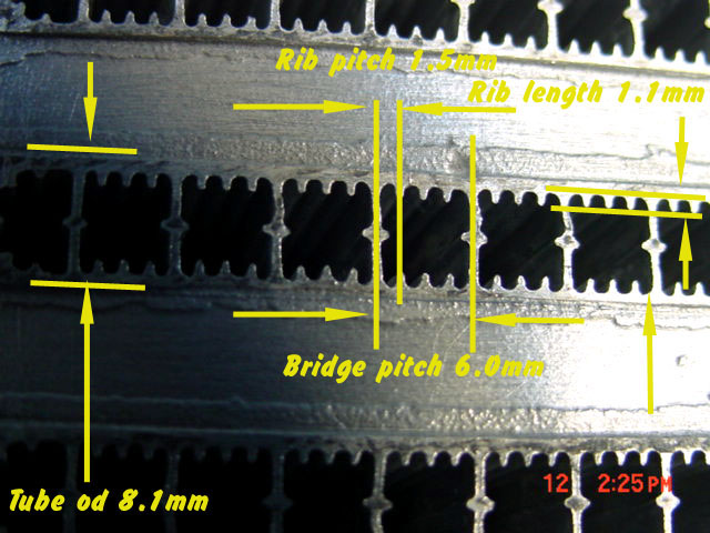
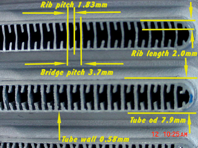
Difference in fins & tubes between K&J
closer & ADRAD cores, even though both are tube/fin |

The extruded tubes. Integral
strength over bar/plate. We remove any swarf before welding or
it's straight into your engine !
|

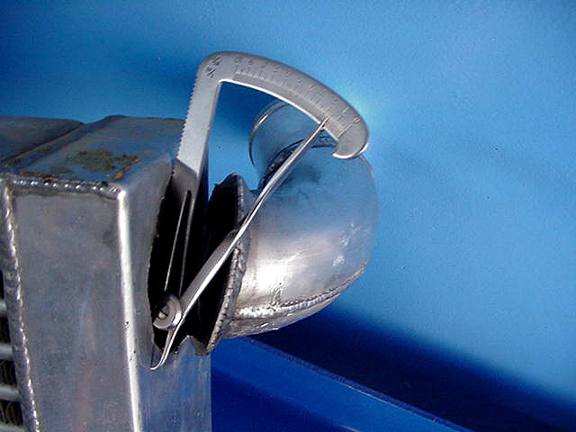
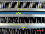
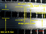
When I was in the factory, we
discussed rib size, flow tested the tubes & this is the result -
1.28mm ribs instead of .80mm
|
Plate tube & fin cores are the physically weakest core in that we have
allot more of them come through our workshop for repairs than any of the
other three, & too reinforce that, they usually have a larger leak for
the damage &/or the leak be further away from damaged area. The core has
three components too each tube. Two stamped side plates with fine folded
fins fused internally. I believe the plates are "stretched" too far to
form the tank on each end, thinning the alloy to where it will crack
with minor stress. They are clamped together (looking like a piano
accordian) & furnace brazed.
Bar/Plate & fin
cores are the second weakest, even though they are also the heaviest
with a couple of the thickest components. However this is the reason for
their weakness. The thin plate side walls have to fuse onto the thick
plate sides to form a "tube", with both of them having to fuse onto the
very thick bars to form the "header plate" for the tank to be welded to.
It is hard for these three differing thickness to be held at the right
temperature for the cladding to melt, ??
& fuse the surfaces together. This is where we see most of the leaks in
these cores, even from new in one brand. The charge cooling fins are
fused to the thin plate walls, meaning there are 5 components too each
tube, a reason that these cores tend to develop a series of weeps along
the "header" seam.
Folded tube & Extruded tube seem to be of similar strength although with
two tube sides, fine fused internal fins & two header plate joints,
folded tube should be weaker with 5 components. However, I have seen
both types of cores come in for repairs quite beat up & out of shape,
without leaking. Eventually the hot/cold & pressure/vacuum cycles will
open up cracks.
The Extruded tube core is possibly the strongest core as it only has
three components in it's construction, a tube & two header plates. It is
also the most consistent performing unit as the internal charge air
cooling ribs are one piece with the tube walls whereas the above three
cores have tubes with fins fused too them & if the specifications vary
in production for any reason ( & it does occasionally), then an area of
fins can exist where they are not in full contact with the tube wall,
bottling up the heat in that area. The same also happens with external
ambient finning, although this is common to all four cores & can be
found with a simple visual/physical check.
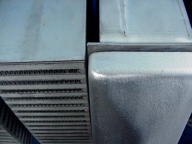
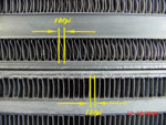
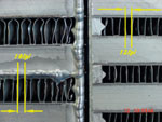
Header
Plate/tube joints, bar/plate joints
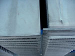
Bar/plate top & tube fin bottom. Note how the
header plate is proud approx. 7mm/side making a wider overall
'cooler. |
Same pair intercoolers from opposite
direction. difference is more graphic. |

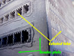
Folded tube/fin on top is okay, tube/fin
bottom left is best & right is worst for air flow entering tube. |
Bar/plate on left has intergral header plate,
whereas tube fine has to be proud to weld tank to. |
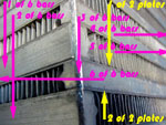
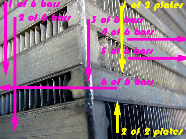
The 8 components that make a complete tube in a
bar/plate core
|
The 2 components that make a complete tube in a
tube/fin core. Note flux/cladding around tube.
|
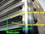
The 3 components that make a complete tube in a
folded tube/ fin core. This has a tabbed header plate to hold
tank on.
|
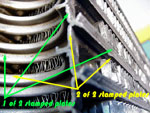
The 2 components that make a complete tube in a
plate tube/fin core, including the tank - shown cut in half
here.
|
I have not worried about fin/ribs in the
above pics. as they are common too the internal structure of every tube
& would unnecessarily clutter the pics. They are highlighted in their
own section.
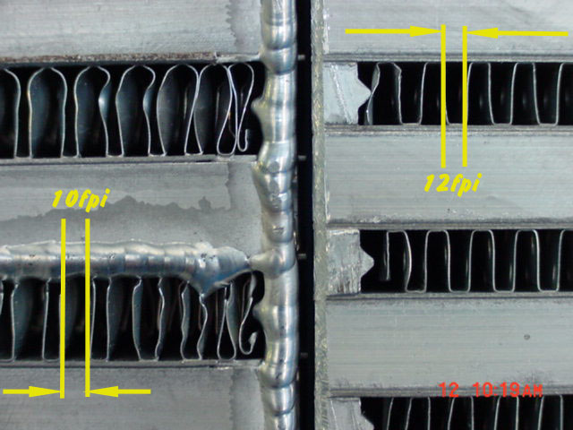
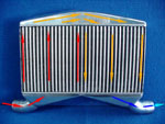
Finning
- or Ribs.
Both Adrad cores. Different fpi.'s for different
applications.
|
Adrad top & K&J bottom, different fin
shapes & pitches.
|
Garrett top & ours bottom. Straighter uniform
fin allows more air through.
|
Charge air fins, straight uniform fins allow
intake charge through with less pressure drop.
|
More open ribs of Adrad give 17% less pressure
drop. Radius on ribs adds to surface area.
|

Longer ribs help pull heat out of air better,
but more restriction.
|

Cut away bar/plate core shows fins at 90 degree
to each other, very efficient but high pressure drop.
|

This is actually an abient air fin, but very
similar to charge air fin. Louvers direct air flow but also cut
flow dramatically, so fpi important
|
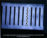
The parts of
an intercooler that do all the "work" are the fins, or in the case of
extruded tubes, ribs. Their purpose is the opposite when in charge air
flow to ambient air flow. In charge air flow, their job is to soak up
the heat in the passing air & deliver it to the tube wall. The trick is
too pull the maximum heat out of the air with the least resistance to
flow. The different designs are flat fin (cheapest & least effective),
punched fin & closely followed by louvered fin (dearest & most effective
at heat soak but with highest pressure drop). Extruded tubes are formed
by forcing an aluminium block through a die resulting in a complex
one piece tube, offering 100% heat transfer between the rib & tube wall.
This does not always happen with fins, because sometimes the factory
does not apply the correct "crush" to the core when clamping in
assembly, resulting in no bond between the tube/fin during furnace
fusion. It appears to be more of a problem with internal fins than
external, but luckily, is not that common. Extruded tubes have internal
walls that form continuous compartments with ribs inside each
compartment. These vary between manufacturers, but the same rules apply
- more ribs/inch, more heat soak & pressure drop. Also the more ribs in
contact with the tube wall, the more efficient. Because of the extrusion
process, ribs are thicker than fins & there is always more open space in
the middle of the tube. This results in a small reduction in heat
transfer if the tube is too long, as the air " straight -ens out"-
reduces turbulence due to the smooth compartment & rib walls. With
Ambient air flow, the fins job is too radiate the heat, so the air
passing through the core absorbs the heat & transports it away from the
core - usually straight into the radiator finning - but that's another
problem! Adrad fold both fin edges over (hem the fin) which doubles the
strength fin & lessens damage. Damaged fins should always be
straightened as they inhibit air flow & so cooling efficiency. The
higher the vehicle speed &/or the more direct ducting to stop
spillage of the air around the core, the closer the fin pitch can be :-
an offroad buggy or hill climb car needs less fpi. than a circuit
racer. Some thought has to be given to radiator cooling or you can
create a problem that can limit the engine output more than the
intercooler can increase it! Intercooler position, surface area, fpi.,
tanks & workload, all have a bearing on engine water temperature.
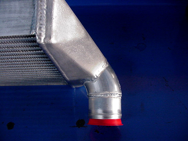
TANKS - the single most underrated part of an intercooler !!!
|
This tank is extremely basic & because the outlet
is in line on the other tank,- even worse! |
This is our tank to do the same job So much more
efficient! How much more expensive? |

Line up of our Hot Chilli tanks. A couple of sizes
still to come. GTR type this end.
|
Note the over hang a tank has to have because of
the construction of tube/fin |

Not all cast tanks are created equal. We could
get our tanks cheaper, but we pay for quality/performance.
|

Our cast tank walls average 3.6mm thick,
negating heat soak problems assoc. with tanks that are 6 -7mm.
|

The areas between the lines are the "tanks" on a
Denso intercooler. The large boundary layer is extremely
turbulent causing a high pressure drop for no gain.
|
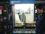
This is where allot of my knowledge comes from,
hundreds of hours testing but hundreds upon hundreds more
fabricating parts too test. Results do not always cross over to
the real world. Alex of Bryant Engineering.
|
The thickness of the alloy in tanks is very
important. Too thin & heat soak is negligible, but their life span maybe
short due to stresses from the continual hot/cool & boost pressure
cycling. too thick & they'll last forever, but suffer heat soak, which
is the time it takes the tank temperature to react to ambient &/or
charge temperature changes. Depending on the use of the vehicle, the
effect of heat soak varies. Constant high speed static throttle
position with a front mount (road transport) is the least effected. A
four wheel drive in soft sand or with a heavy boat up a ramp, fitted
with a top mount, is the most effected. We spent 14 months making
sheet metal tanks for next to nothing while I looked for a good pattern
maker & foundry. It's our customers gain as our tank walls average
3.6mm thick.
Shape or Profile

Most of the charge flows through the bottom 35%
of core, with the top 65% causing detrimental pressure drop
until high boost is reached. Worse again if other pipe is on the
bottom too !! |

The 2 corners cause large eddies & the
square inlet corners small eddies which restrict flow &
distribution across the core window. Worse if pipe is on bottom
other end !! |

Not perfect, but very good & very cost
effective. Nowhere near as important to have diagonally opposite
tanks like both designs on the left. Very small eddies & small
uneven distribution across core window |
Square shaped/edged tanks
are taboo for performance conscious enthusiasts for four reasons:-
1) They look basic,
agricultural & ugly
2) A square edge concentrates
stresses along that fold (or weld), which, depending on several factors,
will shorten the life of the tank to a some extent. It's surprising the
number of small weeps that can go undetected for months, especially if
the turbo seals are good (no oil stains), resulting in a loss of
economy/performance. This usually applies more to a sheet metal tank
than cast tanks, due to their thinner wall construction.
3) Most importantly is that
the square edged tanks hurt air flow & increase "static" pressure drop.
The intake charge does not want to make a sharp turn with the majority
of the air taking a radiused path around the edge, causing some of the
air to eddy back around through an elongated 360 degree tumble. This
causes friction with both the wall surface & the following air, really
hurting flow figures.
4) I don't know if any
manufacturers ever think of this, but when building tanks for a tube &
fin core, if more air is directed to the front or back of the tubes,
then that is how it stays for the entire length of that tube, as the
extruded bridge walls contain that charge & it can't mix until it
reaches the outlet tank, resulting in a cooling efficiency loss. With a
good bar & plate core (not a cheap plain flat fin) this can't happen
because the louvers or holes in the fins allow the charge to pass across
the "tube" as it travels lengthways. This problem doesn't apply when the
inlet pipe is inline (parallel) with the tubes & only applies a little
when big boost is being used.
In our Hot Chilli range of
tanks, the angles & radii of the triangulated roof are different for
each size tank. This is not a marketing gimmick, but shows how important
it is to get it right. Only three degrees sometimes made a difference of
2% of flow but 10% of window distribution.
Configuration
Two designs of tanks are very
poor in distributing the intake charge evenly across the core face.
Please note that 100% distribution is impossible, if the core is high
enough to offer worthwhile cooling.
One design is commonly used on
Rotary powered cars coming out of Sydney. The Core is 500+mm high & has
the inlet/outlet pipes in the bottom of both tanks at 90 deg angle,
parallel to charge flow. However the higher static pressure drop to
cooling efficiency ratio, is less important to a 20+ psi. drag car (it
will increase 'spool up' time! ), but decreases throttle response & a
few kw. output, in a street car. In the pictures (below) of our
answer to this problem, we have designed a dual pass intercooler that
splits the core area in half, so the intake charge uses the whole of the
core evenly. Attention has to be paid the the sizes however, as the air
speed through the core is doubled & if the charge window is too small, a
pressure build up (drop) will result.

4 of 9 tank shapes built to try to
maximize distribution across the core face.
|

From lower down to show some entry changes made.
Front 2 are absolute shockers.
|
In each tank we tried different baffle
shapes/angles & got some mixed results. Some hopeless.
|

In our initial testing, 80% of charge air used
end 25% of core at 264 cfm @ 25" water. Just turning bottom tank
around makes a big difference
|

If the outlet is below this inlet, this is the
worst combination I can think of. Step causes reversion, smaller
diameter speeds air flow & increasers syphoning !
|

This is the second worst combination I've tested
& it's so popular with the Rotary set. ARE has never sold an
intercooler like this - allot missed sales, but we now have a
better setup.
|
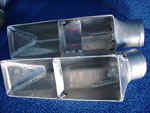
This is our solution too cooling the Rotary.
Maximum effeciency from this large core giving more cooling with
less pressure drop. Relocate the oil cooler & we can make it
even better.
|

Here is how our intercooler looks in the car.
Still fills up the front but gives more overall cooling with a
little less pressure drop. There is a limit to the cfm flow
through these cores & generally need to be thicker.
|
The other design mostly is
used in the USA., where tanks are on the top & bottom of the core,
causing the charge air to make two 90 deg. bends. By using a second
manometer with a long thin probe, we found that 80% of the intake charge
flows through the end 25% of tubes on our first test tank, which was of
reasonable length. Flow rate was good but cooling rate was terrible.
When we doubled the length of the tank, 55% of the intake charge flowed
through the end 25% of tubes & overall flow dropped 9%, indicating that
this design has too have very long tanks, but should be able to be
avoided anyway. We also discovered flow 'syphoning' for the first time
during this testing. The intercooler was making a strange noise, & with
the aid of the second manometer probe, & then removing the tank & using
the old tissue streamer on a stick trick, found that air was actually
being sucked back up the tubes next too the inlet end, by the same
principal as a spray gun operation. This means that some of the already
cooled intake charge was being recirculated through the core again. This
creates a double loss as not only does the extra syphoned air create
more pressure drop, it has already been cooled so takes away core space
needed by the hot air. I didn't waste time measuring the % recirculation
as we rarely use this design. Please note that this paragraph refers to
intercoolers with the inlet/outlet above each other (on the same side).
It is reduced noticeably if one tank is reversed, but still should be
avoided if possible. A dual pass intercooler is heaps more efficient
where both pipes are on the one side, but they require more height for
the core.
A few factors should be remembered
with air flow. Definitely don't polish the inside of tanks or pipes. An ultra
smooth surface causes capillary tension on the surface layer of air with the
wall & will increase drag so increasing pressure drop.
A street car is not in high boost that much of the time (maybe 10% max.- or no
licence, no tyres!), and for possibly 50% of the time in vacuum, with maybe
another 30% at less than 5psi boost, so the engine operates as a naturally
aspirated engine for approximately 70% of it's life. Now, how many hundreds of
hours a year do the Group A Supercar teams spend on the flow bench trying to
find even a half a percent increase in flow? A square edge tank can easily cause
a 20 percent drop in flow, at low boost driving !! Some people confuse the
result of poor tank/pipe design with turbo lag, when it actually may have little
or nothing to do with the turbo's performance. This has been reinforced with our
Air/Water intercooler R&D. program, where much shorter/straighter pipe lengths
are used (reduced "turbo" lag). A crisper throttle response with increased
"driveability" can actually be felt driving the vehicle, very important
not only on the street, but in Rally, Hillclimb, Gymkhana, Jet - boat, type
competitions. In my flow bench testing, I've found that making air flow change
direction by 360 deg. causes noticeably more pressure drop than a 180 deg.
change.
The importance of squared
tanks exponentially decreases as boost pressure increases, this is for
air flow & distribution. If you see a car at the drags that runs 35 plus
psi, with square tanks on it's intercooler, don't worry about it after
the car has launched & is revving out, as power loss is minimal ( maybe
3%), BUT, if the engine could not spool up quickly, or needs nitrous to
spool up, then the tank shape plays a very definite part in this
problem, with Rotary engines seemingly affected more than 4 stroke
engines. I have seen many drag cars, not being able too spool up onto
the converter for 1 to 3 seconds, usually mostly in the afternoon heat -
over cool night air, resulting in up to a quarter track lead to their
opponent. The importance of the inlet tank shape also exponentially
increases with the thickness of the core, from when it is 25% wider than
the inlet pipe, & especially for tube/fin cores.. The outlet tank
only has approx. 40% influence on this as the inlet. I have spent
hundreds of hours on the flow bench with everything from conventional
basic (opposition manufactureres) tanks, to some way out designs that
would be laughed at, but you can't always accurately predict the
results, & it's marvellous what I occasionally learn from these
experiments. I reckon 85% of my r&d. time is aimed at tough street car
applications to provide the most cooling with the highest horsepower
output with the crispest throttle response. Note the word economy was
not used, because it goes hand in hand with crisp throttle response.
Material

Not a pretty sight. Too thin material used. |
A closer pic of the thickness guage. We use 2mm
for hand hammered (formed) tanks without flat surfaces & 2.5 or 3mm
on everything else. |

Macro picture of 3mm sheet metal tank surface.
Fold made with 10mm dia. mandrel. Can see surface cracks if made
with sharp edge folder.
|

Surface of cast tank. Both polish up similar, but
cast takes longer. Can have inclusions or blow holes that will leak
if not cast proper;ly.
|
If the tank wall is too thick is it will become a
heat soak & counteract part of the advantage your intercooler provides.
Worst example is a thick cast tank fitted to a Subaru WRX top mount - or
any top mount. It is getting all the under bonnet heat (around 70°c.) at
low speed & then when nailed, takes a couple of seconds to drop to it's
proper temperature, which isn't that cool anyway. This has much less
effect on a front mount, except when reversing back after that big
impressive burnout & it won't stabilize when staging either. We pay more
for our cast range of tanks, but they average 3.7mm thickness & are well
worth it because of the formentioned problems.
Can an intercooler be too big?
YES ! In street driven
applications, an intercooler can definitely be too big, maybe not for
'attitude', but for maximum performance. It is not an argument to say
that Joe Blow's RX2 runs 9.6 @ 132 with a monstrous intercooler because
that car may run 9.4 @ 134 with an intercooler that is engineered very
close to the overall requirements of that combination. The same may be
said for Fred Nerks TX3 that runs 13.8 @ 100 with his headlight to
headlight monster intercooler jumping out of the grille. The car may run
13 flat @ 110 with a properly engineered intercooler/pipe setup. This is
because if a 13,500 cu. cm. core drops the intake temperature to 40° c.
@ 1.5 psi. "static" pressure drop, a 9,550 cu. cm. core may drop the
temperature to 41°c @ 0.82 psi "static" pressure drop, & I know which
will produce more power !
The closer to ambient
temperature the intake charge gets cooled to, the exponentially larger
the internal surface area of the core is needed, also exponentially
increasing the friction (drag) of the charge air in the larger core,
causing higher Static pressure drop. Please note that the same kw.
output can be generated by two engines, but require two different
intercoolers. If one engine is fitted with a smaller than optimum
turbo, then it will operate out of it's efficiency range, over revving &
'beating' the air, to a higher temperature. Even in a street application
40+ c. (eg. 120 to 160° c.) is common! This requires a more efficient
cooling intercooler, with either larger volume, more cooling fins or
longer tube length, than the other engine that is fitted with a larger
than optimum turbo, which may only heat the charge to 105° c., placing
less importance on the intercooler, but more on the inlet tank "window"
(area) which needs to be larger & the tube length shorter. The first
engine makes a better street driver, as the turbo will be on boost at
considerably lower revs.
A really important point is
that the more oversize an intercooler is, the more important tank shape
is, for both pressure drop & charge distribution across the core face.
Make an effort to suss out the best overall intercooler & pipework for
your car, usage & driving style. It will make a worthwhile gain, &
possibly at less cost!
Turbo Lag ?
or is it
The internet is a great thing, BUT, there are so many false statements that
people make sound so convincing. "I put a big front mount on my VL Commodore
& there's no extra lag at all, it goes heaps better too". Treat this person with
total distrust. The only accurate (note: I did not say honest, because he may be
genuinely kidding himself) part is ' it goes heaps better'. It is a physical &
scientific impossibility, to not have extra lag in this case.
If it was a Skyline or similar car, treat the person with some distrust & quiz
them on both setups, as the system they replaced was certainly not optimized
&/or the new system must be really suited to the car.
-- These figures are calculated for a system with
perfect air flow, without disturbance from poor tank shape, poor core flow
efficiency, gaps in pipes, no. of bends & many more factors, so the actual real
world times will be slower !
-- The actual time a molecule of air takes to travel the
system during , from idle, to 8500rpm., cannot be accurately
calculated as the variables are immense. These four graphs are to help you get a
handle on how important it is to run a properly designed system for street
throttle response & race spool up. This is part of the reason a high stall auto,
turbo, 4 cyl. drag car is usually allot more consistent.
-- Note: -- The smaller the engine capacity - or the
lower the revs used - the more important the design is.
-- Boost has
miniscule bearing on charge air speed/time - it changes the cfm.
output, making the charge denser, BUT not the air speed velocity !
-- The lights on an ANDRA Xmas start tree are 0.400 of a sec. intervals.
-- We have been using these figures (in house developed
computer programme) for years to help us design ic. systems for customers, maybe
that's why so many of our customers speak so highly of the results our products
provide.
-- Following are four PDF files to validate the above.
 |
2.0Litre engine putting out 668cfm. @ 8500rpm.
Core size - 610x278x109mm. 2.5" & 3" pipes. Skyline GTR tanks. 26.853L.
800rpm. -1.673 secs. 8500rpm - 0.167 secs. |
|
|
Exact same engine specs as above.
Core size - 500x278x109mm. 2.0" & 2.5" pipes. Evo tanks. 19.477L.
800rpm. - 1.227 secs. 8500rpm - 0.123 secs. |
|
|
Exact same engine specs as above.
Core size - 150x380x109mm. 2.0" & 2.75" pipes. As our Subaru WRX top
mount upgrade intercooler- not as efficient (at cooling drop) as a front
mount, BUT -- 800rpm. - 0.517 secs. 8500rpm -
0.052 secs. |
|
|
3.1Litre engine putting out 1193cfm @ 8500-remember boost
has no bearing on air speed! All other specs exactly as the
first file above.
800rpm. - 1.079 secs. 8500rpm. - 0.108 secs. |
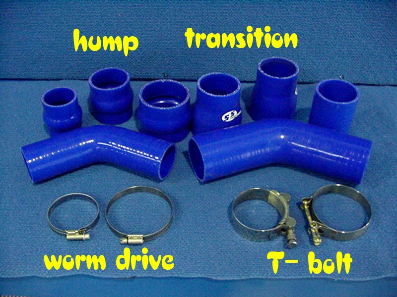
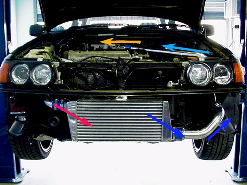
Pipes, Couplers
and
Clamps
I know they're not
intercoolers, but your shiny new $1000 piece of alloy lurking behind the grille
isn't much use without them. Pipes also have to be engineered or they can cause
sizeable pressure drops. The worst thing you can ask the charge air too do
is turn back on itself ie. make a 180 deg turn to the right & then a 180 deg.
turn to the left, like an S shape. Once air is deflected it likes to keep
travelling in that direction. Asking charge air to open out at 360 degrees, as
in a 50mm pipe into the middle of a 90mm flat rectangular tank, causes a
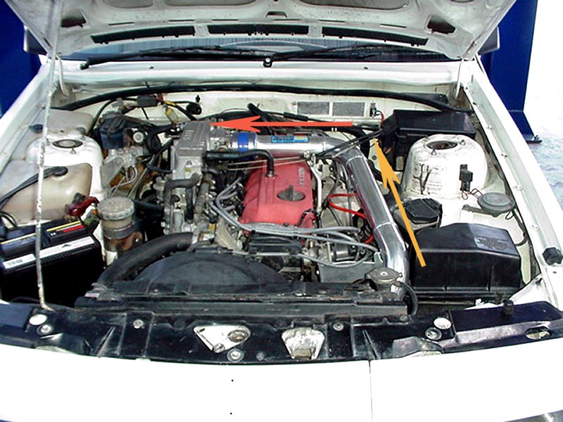
big pressure drop. Another problem is Heat soak, especially when the
throttle body faces across the tappet cover on a north/south engine or at the
rear of an east west layout, making for a long pipe length from the radiator
support panel to the plennum. Why is this a problem? We have measured under
bonnet temps. of over 80° c. & that is not down near the turbo either. On a 26°
c. day, the average charge air temp. out of our front mounts is 30° c. & this
low temp. makes the charge very susceptible too heat soak from the high under
bonnet temp.& naturally, the longer the pipe, the higher the rate of heat
absorption. In these cases, even though we work in alloy predominately, or
stainless, I recommend to do the pipe work in mild steel mandrel bends & have it
HPC (or similar) thermal coated, it is worth the extra time & could be cheaper.
Worst case scenario we have measured between the intercooler outlet & the
plennum inlet, is 21° c. (a 25° day) on a Commodore VL with the pipe behind the
radiator, with a guy in Cairns telling me he measured 26° on his Skyline R32
GTST
When it comes time
to by couplers, if at all possible, pay the extra money, buy the proper high
temp. silicon ones (they look good), fit them & forget them, after you retension
the clamp a week later, they do shrink under the clamp compression. I know hump
hoses cause a little pressure drop, but that can be better than cracking pipes
through not having enough give in the system. If there is only a short distance
for the pipe, & it is between a fixed point (intercooler etc.) & the engine, use
one or two humps too allow for engine movement.
Clamps are important
in both sealing & longtivety of the couplers.
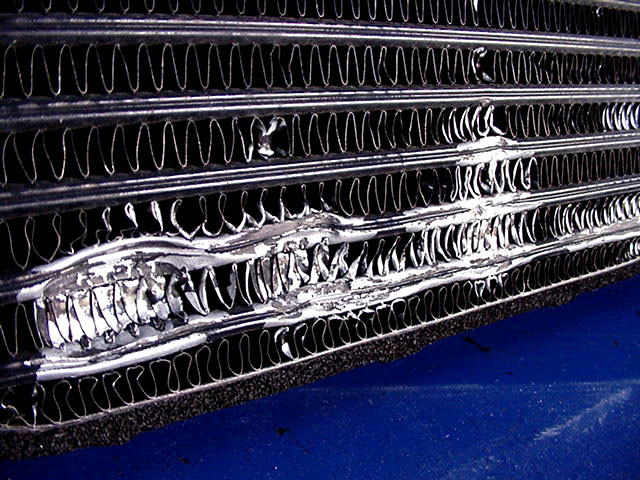
Intercooler Maintenance

This is the worst picture since 1997 of one of our
customers horror story. |

Enough too make you sick !! |

Japan really must have terrible air. The black buildup
actually corrodes into the alloy & must be cleaned.
|

This is how it should be. Back to near new efficiency,
& looks the part.
|
An intercooler that has been
in service for a couple of years (longer in rural areas), will
definitely provide more cooling if it is cleaned properly. That is,
soaked in a degreaser bath to remove the interior oil film that has
accumulated (which may be ever so thin with a new turbo), then power
flushed with water. The exterior fins should sprayed with a proper
aluminium etching cleaner to remove the surface oxidation & road grime
that will have formed. Both the oil film & oxidation/grime buildup
provide insulating coatings that inhibit the transference of charge air
heat to the ambient air.
If not sure of the proper procedure
& products to use, we strongly recommend having this done by a professional
business in our field. Please see the two pictures above left, which is a 9
month old intercooler that was removed off the car for another reason, & the
owner decided to do the right thing & clean it to be sure of maximum
performance. He rang us & I told him we use a Degreaser, Kero & Phenol solution
in our bath. He already had some degreaser at home, so bought some kero, mixed
them, blocked off one end & poured the mix in to let it soak. It started to get
warm after a short while, then bubble gently & get hotter. By the time he
realized it was going awfully wrong & tipped it out, this was the result. It was
late Friday afternoon when he rang, both of us were in a hurry, I
didn't say & he didn't ask about different sort of degreasers and he
didn't read the label which said 'not for aluminium'. It was a water
degreaser he had & mixed with the kero. The caustic base of the degreaser
attacked the alloy & rendered the core completely useless, a new core being the
only alternative - expensive mistake for both of us, as we helped him out with
the cost. I rang a few industrial chemists & the answer was the same from them
all - over the left shoulder. For internal cleaning, only
use a petroleum based degreaser, which we mix with Kero & phenol.
Specific acid cleaners must be used on the external cooling fins as the average
thickness is only 0.08mm - that's paper thin. Any bent over fins should be
straightened before the cleaning process, so the fin is cleaned properly &
full air flow is allowed through the core.
Check all the mounting brackets,
both on the cooler & car for any signs of cracks. If you have to undo or loosen
any bolts, take notice that the brackets don't 'spring' or have tension on them.
If so, fix the problem so the bolts go straight in easy. This will stop any
stress cracks forming or spreading.
Check all the hoses for any signs of
deteriation, especially next to the clamps & in the centre of any convolutions
if the hose has them. These are by far the two most common problem areas. When
buying hoses, do your car a favour & pay the extra for proper high temp silicon
hose. Buy it once, fit it once, & forget it (after checking clamp tension after
a week). Remember that hoses shrink under compression of the clamp, so when
reassembling, make sure that the clamp not only goes back in the exact same
position but also around the same way, as the tabs under the worm drive
mechanism are asymmetrical & could allow charge air too escape. Same with
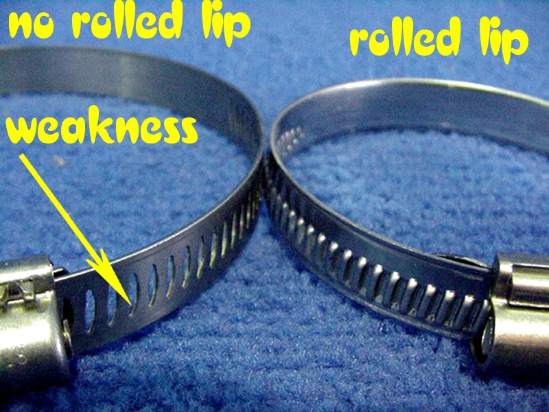
radiator hoses too. When buying clamps, always make sure the band part has a
rolled edge on both sides, this stops cutting the hose with time, as they must
be very tight if boost is over 10 psi. If over 20 psi. I recommend using the
T-bolt clamp.
One really top, time saving trick I
was given by Matt @ Chiptorque (Nerang) is to plumb an air line set at a couple
psi into the inlet system & listen or feel for the leak if you're having trouble
tracking it down or have doubts. A small leak is next to impossible to diagnose
with the engine running sometimes.
Repairability
This oe Nissan GTR core does not leak. Because
there are no sharp creases in the damage, it will probably give
several years service. |
This Skyline GTST is going for scrap. Tubes
probably don't leak now, but tubes torn out of header plate &
tank holed.
|
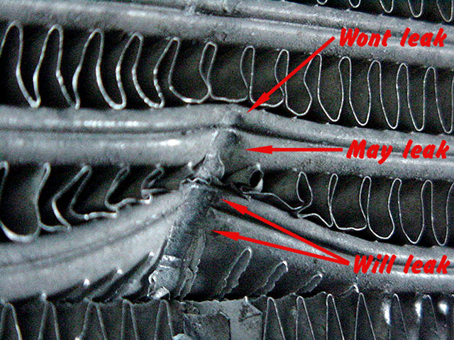
Close up of damage. If "will leak" tubes aren't
leaking now, they soon will with hot/cool & pressure cycling
|
|
When considering tube
construction, one thing to remember is the strength & repair ability of
the cores. The weakest core by a very big margin is the plate tube & fin
core. We get allot of these through our workshop (including oil coolers
of the same construction), but they are relative easy to repair as they
mostly crack in the centre of the end tank concertina joins. If
the crack is in the centre of the "tank" end, then it is a throw away.
They have to be hydrogen brazed as the heat from TIG welding is too
concentrated, usually resulting in a weep at one/both ends of the welds.
Bar & plate cores are weaker than tube & fin. The worry is that
Garrett paperwork says that it is acceptable to have leaks in the core,
as long as it doesn't exceed 4 psi drop from 30 psi in 15 secs !!!
We may have had a leak in a tube & fin core over the years, but no
new intercooler has ever left our shop with a weep, let alone leak.
Bar & plate cores are very difficult to repair leaks anywhere on them
because of the vastly differing thickness components , but tube & fin
are only hard when the leak is in towards the centre of the core by more
than 15mm.. The wall thickness of an Adrad core is 1.3mm
front/rear face & 0.7mm for rest of tube and K&J is 1.0mm front/ rear
curve & 0.4mm sides of tube. Any competent aluminium welder will be able
to weld damage to the tubes, but burning the fins away will sort out
their talent ! This advice is from
our workshop, that is one of the few set up too repair properly as well
as fabricate new assemblies - in fact there is not another shop in
Australia, set up anywhere near as comprehensive as us, for repairs !
Chinese Intercoolers
I've tried to stay out of this as long as I
could otherwise it would come over as blatant sour grapes, but there is
now enough knowledge & enough people have been caught to substantiate my
findings & most importantly, the rush of blood from both sides
(particularly on forums) has mellowed abit. There are allot of myths,
doing the forums in particular, ranging from close to right, too
downright ridicules, so I will try to keep to facts.
1) Our intercooler sales are down near 60% to what they were 2 years
ago, so they wounded our business for a while. However our
intercooler dollar turnover is only down 20%, because we are making more
thicker units for the higher powered cars that are being built, & our
air-water sales are increasing too.
2) ARE can not have a core made in Australia within $90.00 of what we
can SELL a complete Chinese unit
for. I saw an SBS documentary on Wal Mart in USA's purchasing policies &
they stated that a Chinese factory worker is paid as little as $0.78 per
hour. $20.00 per hour is an average type wage in this business & what
ticks me is that a whole heap of the Aust. workforce (Doctors. IT, etc.)
would not even work for 100 times the Chinese wage. Lets not even
mention 4 weeks annual leave with 17% loading.
3) Not all Chinese intercoolers are created
equal. I can not stress this enough ! They do not come from
the same factory. There are at least 8 factories that have contacted us
with total different addresses & then there are different named
companies within these addresses, which is how some flaunt the copyright
laws that western compan - ies must abide by. A couple of factories make
very good units, some are okay, & some are downright bad. To complicate
purchasing further, some size intercoolers from the same factory are
good & other sizes bad. How do I know this, we tested some 75mm units
from an importer, which came up good in all aspects & unfortunately for
us quite good in a couple of aspects, so they represented excellent
value.
We have sold a few of these without one complaint. They also imported
some 90mm & 100mm intercoolers from the same factory. After getting some
returned with vocal complaints because power output & response dropped
when these were fitted (often replacing a 75mm unit), they sent one each
up to me for testing. Just looking at them showed a close fin pitch.
Results are listed below. We are talking all bar-plate construction with
these imported intercoolers. The sad part of all this is there is no way
of accurately listing who's who, most factories will stamp any name onto
there product!
| Intercooler - Size |
Type |
Flow Rate-corrected |
Notes. |
| Chinese 600x300x90mm. |
Bar-Plate - 3" inlet. |
299.3
cfm |
|
| Chinese 600x300 x100mm. |
Bar-Plate - 3" inlet. |
330.9
cfm. |
|
| ARE-610x302x91mm. |
Tube-Fin - 3" inlet |
471.4
cfm. |
|
| ARE-610x302x91mm |
Tube-Fin - 3" inlet |
493.3
cfm. |
With our optional venturie plate option |
4) A few intercoolers have weeps, or sometimes leaks, out of the box,
which makes me think that they will develop more leaks ( maybe
even if they don't have any when new) early in their life, with the
rigors of hot-cold / press-ure - vacuum cycling of normal use.
5) Our testing & feedback from some reputable dyno shops suggest that
the majority of Chinese 'coolers do a good job up to the point of being
worked hard & then gains exponentially taper off. A couple of years ago,
they generally had a basic fin design @ a course pitch in a small
'tube', meaning they had a low pressure drop but not good cooling
efficiency, so do a good job for an engine with an efficient turbo
operating in the low-middle of it's efficiency map. Try & run too much
boost & they will 'choke' & pressure drop will soar. The later
trend seems to be much closer fin pitch, but still in a small 'tube',
restricting flow even more, & worse still 'choke' more at a comparative
lower boost. The closer fin pitch which gives better cooling rates,
would only increase performance if the tube length was shorter, as the
cooling efficiency quickly exponentially decreases (we have placed
probes @ 100mm increments along tubes of both air-air & dry ice
intercoolers) & the pressure drop (more slowly) exponentially increases
along the length of a tube, meaning there is a 'sweet spot' where
cooling rate & pressure drop give maximum performance. Sorry guys, but
our parchment 'for big is better' philosophy & the fact that the Chinese
factories don't seem to have much technical inkling of how an
intercooler works, means that allot of purchases will never give near
the gains possible & some, well, they're just a waste of your 'cheap
money' !!!
6) They really have there place in the market, are very good for anyone
seeking a moderate power gain with a limited budget & for more gains
than this, become increasingly more difficult to gauge if they will do
the work you need , all this - is of course if
you get a good one !
Import or 'Grey' Intercoolers
These are a much preferred
option to the Truck intercoolers, talked about below, in fact, some very
good units can
be bought for a value price. If the unit has not been stored properly
after it was removed from the vehicle (& this means in the wrecking yard
in Japan, loading onto & in the container coming over here & storage
over here), then it may in fact, cost you money &/or performance. They
have been brought in to us for cleaning with a line of whitish powder
1/4 to 1/2 way up the core internally, from where they have been laying
in the salt water coming over. Don't touch them. Sometimes, they have
looked real good, but after we have soaked them in the bath & while
power flushing, the amount of pebbles, dirt, & the odd self taping screw
that comes out, is a real worry. Firstly, too us that we have got all
the rubbish out, & secondly, that anybody buying one & fitting it
straight up, has been lucky & it is clean, or else whatever is in there,
will finish up in the engine sooner than later. Paranoid? no, seen
it happen too often.
If an import intercooler is
for you, then look for a unit off a car that has at least 50% more power
than your engine, as oe. intercoolers are sized by accountants, not
engineers. Even if the engineers do get the final say, I'm sure they
know how much some of you guy's will turn up the boost & so have a small
intercooler to try & "choke" your gains !
Truck Intercooler Cores
There are differences
between a 'truck intercooler' and an intercooler fitted into a
performance car application. However, 'truck intercoolers' is a
broad term and does not sufficiently categorize the product. Just
like other types of products, truck intercoolers come in different
configurations - both bar and plate and tube and fin design. I
have not seen a plate tube & fin core in a truck, they would be too
weak. However, due to their specialized application, truck
intercoolers have a noticeably courser internal fin &/or external fin
pitch (depending on whether tube and fin or bar and plate), than their
cousins fitted into normal performance car applications. This means that
although a new truck core can be used in performance applications, the
core surface area/volume must be larger in proportion to that of a
standard 'performance core', & then it will give good temperature drop,
but it will be at the cost of a medium/ high "static" pressure drop &
higher radiator water temperatures.
A truck intercooler core is
nearly always larger because even though the engines are slow revving,
they have a large swept capacity requiring a high cfm. intake charge,
also there average road speed is much slower & the engine is under load
most of the time. Because of the slower road speed, thinner cores per
area and with less fpi., are used to keep the air speed onto the water
radiator as high as possible. 37mm thick is used by truck manufacturers
in there lower powered applications, but you hardly ever see them in a
performance application. Trucks also have a large frontal area, giving
more room for the intercooler/radiator.
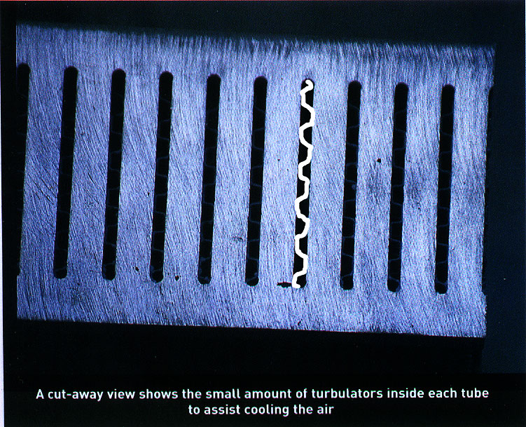
We cleaned out a Volvo truck
intercooler (it had plastic tanks) & during the job, discovered that it
had no internal fining, turbulators, nothing, inside the charge air
tubes at all. When the customer came to pick it up, I asked him how it
going on his car (Cordia), & he said brilliant ! He had never measured
the temperature drop, & I guess he drove pretty easy, so it may do a
reasonable job, but put it on a Commodore & it would be hopeless.
The larger volume of a truck
intercooler has three main drawbacks:-
1) Higher 'static' pressure drop
2) Increased 'turbo lag'
3) Higher engine water/under bonnet temperatures - in front mount
applications, as the large truck intercooler blocks more of the air flow
through to the radiator.
Therefore, if money is a
major issue than new truck cores in a performance car are a viable
BUDGET
alternative, especially if tanks can be made & fitted at "mates rates"!
Used Truck Intercooler Cores
It is my opinion that used
truck intercooler cores should not be used in a performance car.
Using a used truck intercooler core is a huge gamble, are you prepared
to risk the welfare of your engine because of a cheap intercooler.
Why put a $100 core in front of a $2000+ engine? It also is a slow job
to do properly, as compressed air has to be blown through the tubes,
from the opposite end to which you are working on.
Most truck intercooler cores
can fit into a performance car application, but they nearly always have
to be modified. During this modification process, whether it be
when the old tanks are being cut off, or when the core is being cut down
in preparation for welding tanks on, or when the tanks/core is being cut
down, swarf and fillings can get lodged in the core, some of which can
be up to 600mm in length and can be imposable to blow or clean out.
The result is that they dislodge days or weeks later, after working
their way through the intercooler tubes and intake piping and end up
passing straight into the engine. I'm sure you can imagine the
result of that !? Another point is that bar & plate and finned tube
cores are much, much harder to clean any solid particles out of as they
get trapped in the fins & have to "travel" through the length of the
tube, interestingly, the exact same reason why per sq. cm., these cores
dissipate heat better, but at a higher "static" pressure drop.
Remember that a used truck
core is for sale for a reason. If you buy one, hope that the truck was
hit up the arse, because if it was hit around the cab, then the core was
more than likely damaged or twisted to some extent. If the damaged
section was cut off, your core will still have some stress & 'set' in it
& even if not leaking when purchased, the heat & cutting when modifying
it to fit, may release the stress, resulting in leaks in the header
plate/ tube joints when finished. We do not do this work anymore for
this reason, it happens far too often !
Picture of core in test tank.
Used truck cores in a
performance car are a stupid, desperate alternative, & if you haven't
guessed, a pet hate of mine. Use them in your smoky turboed A12 powered
rusty 120Y, but please not in a performance car. I'd much rather see you
buy from an opposition shop !!
Last words.
Intercooling a forced
induction intake charge is a compromise. We direct all our energies &
R&D., at minimising the negative compromises & maximising the positive
compromises!
A 20% gain in air flow through
a component, does not give a 20% increase in power - I wish it did ! It
might only result in a 0.5% (or 5%) gain in power - it all depends on
the application.
If you have read this far, I
thank you kindly, because it has taken me allot of work. I've tried to
be as honest & unbiased as I could, so I really hope you found it
both worthwhile & especially educational. Spend your money
wisely, & you'll always be ahead.
Short Glossary
(for a our full edition
click here)
* "Static" pressure drop -
The measurement of the drop in pressure of the air travelling through
the core, friction or 'parasitic drag' measured on a flow bench (of
capable capacity) at ambient temperature.
* "Dynamic" pressure drop -
The measurement of the drop in pressure of the air travelling through
the core, friction orO 'parasitic' drag plus the drop in pressure caused
by the cooling of the intake charge (closer molecular structure of the
particles resulting in a denser, smaller volume exiting) due to the
mechanical design of the intercooler, or in more engineering
terminology, thermal matrix heat exchanger!
|