|
In July 2003 we increased
the parameters substantially & added a few new fields to
our in house developed computer modelling programme for
air water intercooling. We had only logged data
from 420 rwhp but we had already refined the programmes
accuracy to the point of being sure our figures
would be very close in the real world. After much
heartache, pain & money, it all came together for Craig
& Rob at the '08 Nats (yes - 5 years) & although
they didn't make the 2000hp, just on 1900rwhp has
vindicated the accuracy of our programme.
I do not know of any other
fabricator / manufacturer that has a programme anything
like this. We can accurately predict the results of our
air/water intercoolers fitted to your vehicle, so you
can have faith in knowing what the results are going to
be before you spend your money. Please check the
original '03
PDF
file below. |
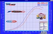
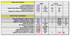
SUMMERNATS 2008 HORSEPOWER HEROS
|
 Note 1
 |
|
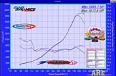
| Third - Gary Pope
-
BLO 402 -
1529rwhp |
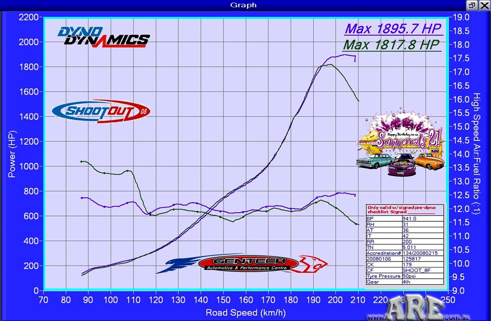
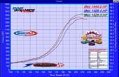
First - Craig Munro -
Try Hard -
-1895rwhp
-
note almost overlay of back to back power curves |
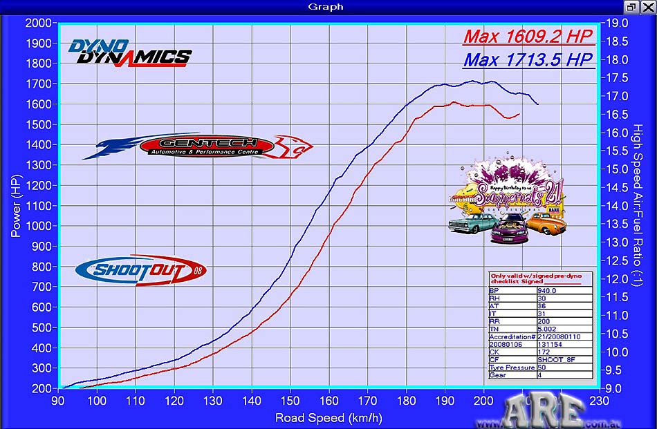
Second - Lyle Lemmon - Mr PSI -
1713rwhp |
Note 1 - the sudden drop
off in power at 192kph is a boost loss issue that is suspected to be
blow off valve related, as the valves control the boost - now being
changed too waste gates control as mid 30 PSI is the maximum boost
available with the setup as run here ! The run was on track to make
even more power !!
The above three cars have a number of
things in common.
All the above graphs were achieved in a room @ 36°c & are rear wheel
horsepower.
They are owned by dedicated enthusiasts.
They were mostly built by the HorsePower Factory
www.hp-f.com.au -
overseen by Rob Vickery.
They were all tuned in house by Amberley Autos
www.amberleyautos.com.au
Their intercoolers were computer modelled & then fabricated by ARE
Cooling .
The owners are now much poorer than before they started.
| KPH |
RWHP |
HP diff. |
% dif. in 2 |
HP inc. |
RWHP |
HP diff. |
% dif. in 2 |
HP inc. |
RWHP |
HP diff. |
% dif. in 2 |
HP inc. |
| 100 |
185 |
- 10 |
- 5.4% |
|
230 |
20 |
8.7% |
|
205 |
15 |
7.3% |
-- |
| 110 |
200 |
- 20 |
- 9.5% |
|
270 |
40 |
14.8% |
|
260 |
10 |
3.8% |
26.8 |
| 120 |
225 |
- 25 |
-12.5% |
|
320 |
40 |
12.5% |
|
330 |
5 |
1.5% |
26.9 |
| 130 |
270 |
- 40 |
-17.2% |
|
400 |
60 |
15.0% |
|
430 |
5 |
1.2% |
30.3 |
| 140 |
305 |
- 40 |
- 9.4% |
|
535 |
110 |
20.6% |
|
585 |
20 |
3.4% |
36.0 |
| 150 |
370 |
- 60 |
-15.3% |
|
745 |
190 |
25.5% |
|
740 |
15 |
2.0% |
26.5 |
| 160 |
490 |
- 80 |
-16.6% |
|
1065 |
210 |
19.7% |
|
880 |
15 |
1.7% |
18.9 |
| 170 |
690 |
-170 |
-21.4% |
|
1340 |
120 |
8.9% |
|
1005 |
5 |
0.5% |
14.2 |
| 180 |
1000 |
-200 |
-18.2% |
|
1530 |
150 |
9.8% |
|
1340 |
5 |
0.4% |
33.3 |
| 190 |
1175 |
-110 |
- 8.4% |
|
1645 |
110 |
6.7% |
|
1710 |
20 |
1.2% |
27.6 |
| 200 |
1430 |
- 65
|
- 3.9% |
|
1645 |
110 |
6.7% |
|
1820 |
90 |
4.9% |
6.4 |
| 210 |
1460 |
- 20 |
- 1.1% |
|
1600 |
100 |
6.3% |
|
1630 |
350 |
21.4% |
-10.4 |
| |
|
|
|
|
|
|
|
|
|
|
|
|
To be continued

This was originally uploaded to our site in late 2004
!
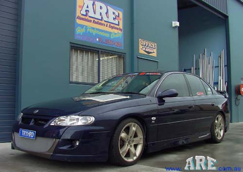
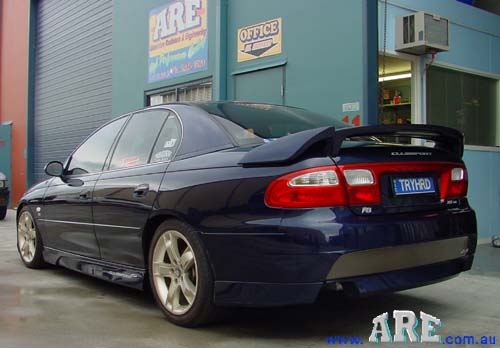
WhaT'S
the big deal
with this car ?

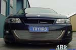
near standard
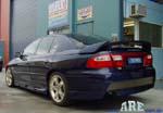
'sorta' standard
very standard
download the Summernat's 08 run here (right mouse click and save as)
M A Y B E 2000hp
(1500kw)
???
Please note that this
is what our system is designed for, what owner - Craig Munro
www.hphero.com
would obviously love to make, what crew chief - Rob Vickery is aiming for
& what we're all hoping Amberley Autos/Horsepower factory
www.amberleyautos.com.au Marty can tune this beast to. The biggest
worry in this equation is the Pump fuel - 98 ron. I have no doubt in my mind
that these power levels are obtainable with C16 or equivilent, but optimax is
going to take an exacting level of tune & cold charge air.
M A Y B E
T H I S ! ! !
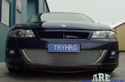
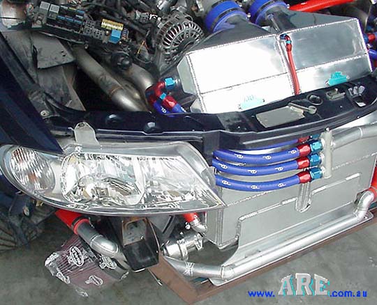
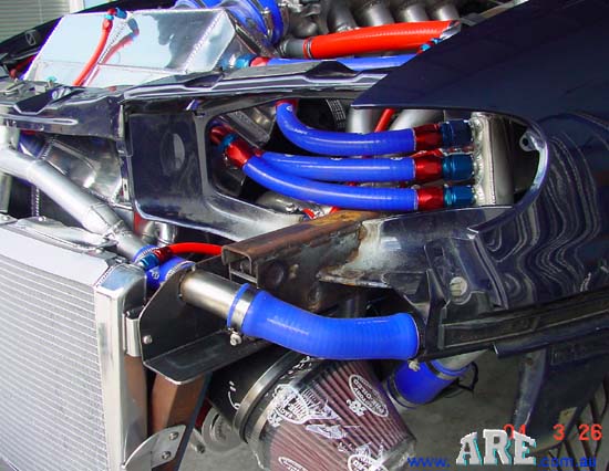
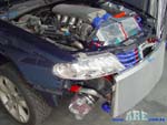
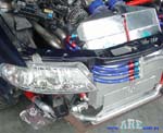
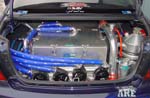
Note that hoses are colour
coded throughout the car.
Red is Heated water.
Blue is cooled water.
 |
 |
|
 |
 |
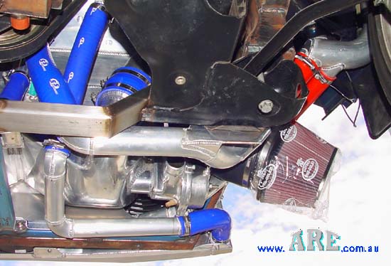
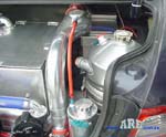
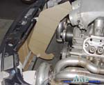
Equal amounts of chilled water into both sides of the intercooler. |
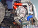
The blow off valve is nearly as big as some cars turbos ! |
|

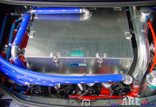
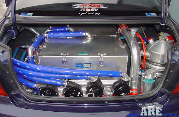
This is the ice chiller. The boot is the only area big enough to
hold enough ice to absorb the heat from the front a-w. ic. |
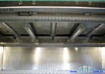
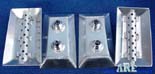
This is the underside of the ice chiller box lid. All hole positions
& sizes are calculated - not guessed. |
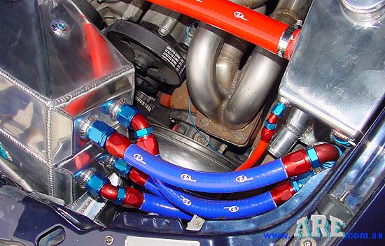
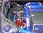
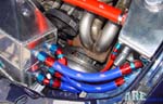
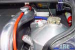
I reckon the unusual mix of speedflow alloy AN fittings on SFS
silicon hose, that we pioneered, looks real trick. |
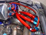
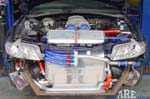
Cold water in the blue hoses in & hot water out the red hoses out. |
|
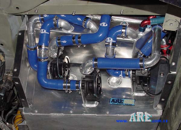
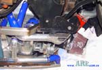
4 DC. engine water pumps push minimum of 180l of chilled water up to
the engine bay. |
3 SX fuel pumps push fuel up to the engine, Thru our ice chiller
sump. |
 |
 |
|
 |
 |
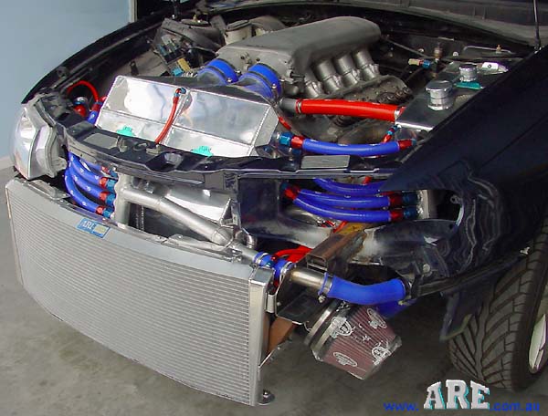
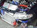
Definitely not your average cooling system. Curved rad- iator is to
allow air from 3 fans to escape. |
We used a mixture of alloy tube & silicon hose for best water flow. |
|
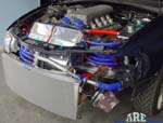
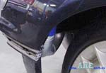
With the cover on you'd never know what's underneath. |

These three D.C. pumps are to recirculate the ice chiller water
only. Need 150 l / m. flow. |
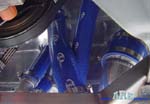
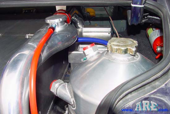
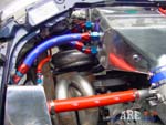
3 silicon hoses in centre carries very cold water & single hose on
right, bloody hot charge air. |
|
|
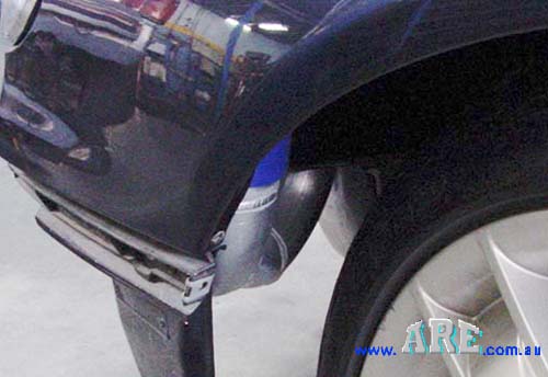
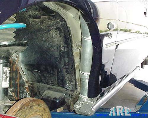
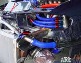
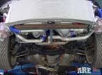
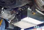
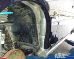
When the side skirts are fitted, this is all that can be seen to get
180 l/m. of water from the boot to the engine bay. |
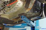
The side pipes had to be welded in an oval shape to allow the side
skirts to fit. |
Link to our new
DRY ICE RACE intercoolers
and
T H I S is
how we made it
!
A six page PDF file |
This is the first stage of the
project. It is the PDF file of our ARE computer
programme sent to Rob & Craig with the projected results of the system
we designed. This was July '03. Not too long now before we know how
accurate it is! We use a ±5% allowance with our temperature.
Please note: There are hundreds of lines of calculus that are
hidden in our programme & the solid coloured cells are to prevent cross
referencing of data in different files on our site. There's more here
than I should give away anyway. |
 |
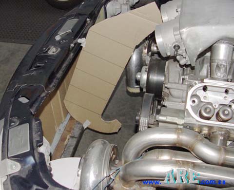
This is the second stage before we
attack any alloy. Cardboard templates to make sure it's all going to
fit. As it turned out, the top two matrix had to be reduced because of a
four mm. interference that we could not get around |
|
|
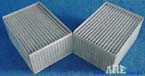 |
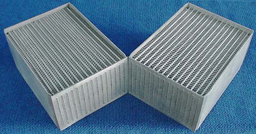
These are two of the eight core
matrix used in the intercooler. They are our brand new tube extrusion
that delayed completion of the car. |
|
|
 |
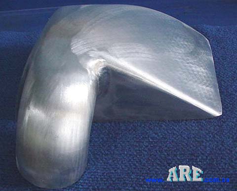
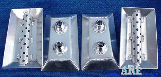
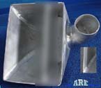
They may look straight forward, but
there is a total of at least 25 hours work in this tank , &
both would have to be different ! |
|
|
 |
It took 3 times on the flow bench to
get the distribution pattern I wanted Yes, it does cost pressure drop,
but the cooling gain far out- weights this. Every joint is double welded
for strength. The start position & profile of the baffle is most
critical. |
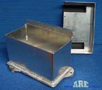 |
This is the battery box we had to
fabricate. |
 |
Seamless transition from the mandrel
bend to the tank roof. The external fillet weld pattern is left
because it has nothing to do with performance & can't be seen. There is
a limit to wasting time. |
 |
Craig wants to be able to take his
mates for a skid in comfort & wouldn't let us run 2x2½" water pipes
through the cab, so we had to do this. Added a few grand to the price,
so I hope his mates enjoy it - they're eyes will be tennis balls |
 |
Nothing about this job was straight
forward. Maybe a spray pattern is overkill, but it all helps. |
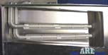 |
These are the fuel pipes running
through the ice box sump for extra cooling. |
 |
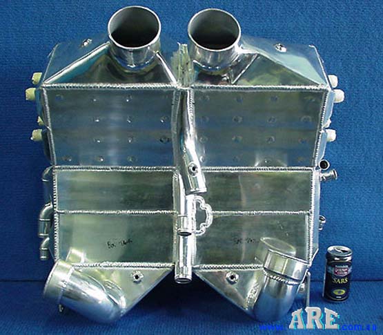
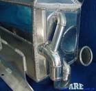
This sucker should remove 410kw. of
heat out of the intake charge. The air speed thru each inlet pipe is 205
kph, but we've got it down to 29kph thru the core !! |
|
|
 |
The water out of the two bottom
cores, is going to be at a minimum of 104°c ! They will remove 79 kw of
heat each. Note: the last 2 cores (top) only remove 8kw each. |
|
|
 |
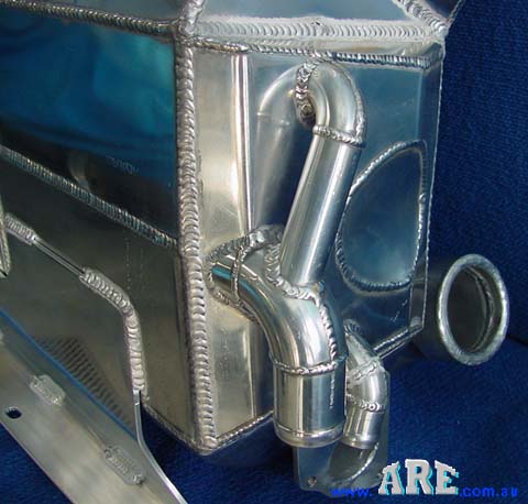
The pipe shape is to fit everything
in Same for cutout in water tank. Id of every pipe is calculated for the
right flow rate. |
|
|
| |
|
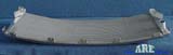 |
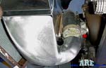
Shows the curve we had to put in the
Radiator core to fit in the front This car has to cruise! |
| |
|
 |
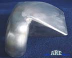
So naturally the fan shroud curve
had to match. |
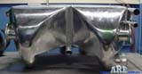 |
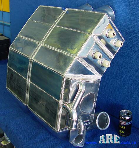
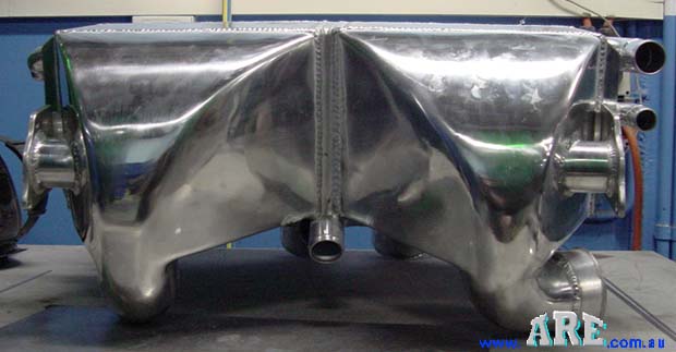
When I saw this on my welding bench,
I just had to nick name it 'the fat arse cooler' ! It wouldn't
fit into even my pants. |
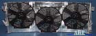 |
Finished fan shroud-fan assembly. 3
x 14" DC. fans provide 3324 cfm of ambient air flow. Oh, be wary of some
of the figures claimed. We've tested heaps !!! |
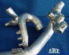 |
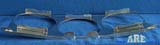
These are just two of the many pipes
we had to fabricate for this car. |
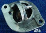 |
Some of the work we had to do on the
thermostat. Yes it has to run one - definitely! Same as every modern
car. Since alloy heads came in. |
 |
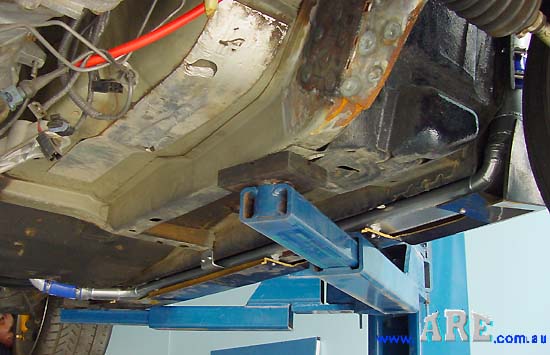
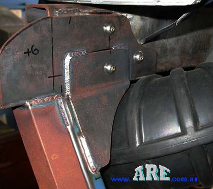
This is the bracketry we fabricated
for the intercooler bottom mount on to the chassis rail. It has to
support a dry weight of 48kg. |
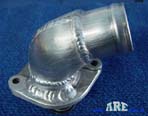 |
Finished thermostat ready to fit. |
|