|
AIR / WATER
Intercoolers
|
I
don't know how I can stress enough how unique
& accurate our in house computer programme is for
sizing air-water intercoolers, but please take the
time to look @ Heath Lawson's
PDF
file & Craig Munro's
PDF file, & then the results acheived. |

I believe this
is the biggest, most
efficient automotive air/water system fabricated to this
date. It is definitely the only one that was computer modelled
before starting, & so far, has performed within the parameters
as given to the tuning shop -- our 'in house' programme truly is
that good !!
It has it's
own page so click on any of the 3 pics to open.
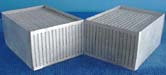
These are our first
cores with our brand new tube. There is a bunch of heat
dissipation here !
There are 52
pictures & 18 graphs on this page.
 |
 |
 |
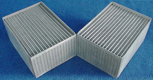
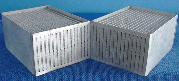
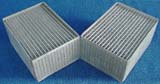
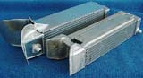
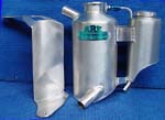
| These
are the 4 different cores we have tried in air/water
intercooling to arrive at our own new design. From
the left - Spearco bar/plate, K&J intercooler, K&J
oil cooler, modified dimple radiator, & our new
core. |
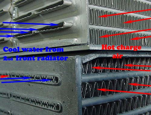
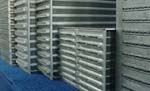
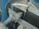
This is
a close up of the modified dimple wall radiator
cores we used in our 3rd generation a/w intercoolers
on top of our new tube. Very good but really had to
have heaps of water forced through them - not enough
water to the charge air ratio& to thin wall
thickness. |
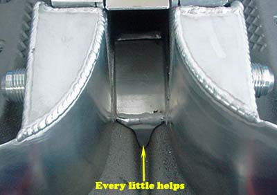
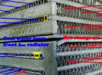
This is
a close up of a spearco bar/plate on top of our new
tube/fin a/w core. Note the BIG difference in
material thickness & surface area for heat soak - in
yellow. The b/p core was similar (but better) than
our mod. radiator cores. The coarse fin pitch on our
core was made for a reason. |
We started
testing our first generation air/water intercoolers in early
2000 -
project rodeo
- after 12 months of research. Up until then, AVO was the only
company commercially manufacturing air/water units in Australia.
Our units were made with modified tube/fin intercooler cores, &
even though they did a good job, we realized that they had too
large a water tube to charge air window ratio.
Our second generation 'cooler
came on line in '01, made with a modified radiator core -
project Hi Lux
- & while it was an improvement in most circumstances, testing
in a number of vehicles proved that we had gone too far the
other way, with not enough water for the charge air ratio. We
had to oversize the pump to get good cooling.
AGAINST -
Complexity & Cost.
You need a second radiator, water pump & preferably some form of
pump speed control, 2 speeds will do the trick. They are much
harder to size, this is why we have pumped hundreds of hours
into data logging & creating a sizing spreadsheet programme.
Under the same circumstances, drive in/out will be approx. 20 to
60% dearer.
It
also became apparent after a couple of years testing that I had
to down grade my initial cooling estimates of air/water
intercooling, which is a disappointment, but necessary. I
thought that I could design a system that at speed, would cool
the charge air within 4ºc of a front mount - both systems being
equally engineered. It appears 8 to 12 ºc is a real world
figure. Please put this into perspective. A 'front mount' car -
Skyline GTR, 180 - 200 Sx, Supra etc. will give results on a
25ºc day of 31 - 36ºc into the plennum. An air/water setup will
give 42 - 48ºc under the same circumstances, but a 'non
front mount' car - Skyline GTS-t, VL Commodore, Subaru - any car
that doesn't have a front facing throttle body towards the
radiator support - will give similar temps. due to
heat soak in the long return pipe from under bonnet heat -
approx 70 + ºc, even though the charge air in both air/air
setups, exits the 'cooler at 31 - 36ºc.
FOR --
Now, the above paragraph is the only time a front mount will out
perform an air/water if both are set up properly - at speed .
Stop/start, drag racing, towing, 4 x 4 offroad etc. all gain
from air/water. The charge air temps. into the engine are also
much more stable with logging showing a spread of 35
to 40ºc around town & 35 to 50ºc laden in soft sand, 2nd gear
low range, whereas, front mounts have logged 30 to 65ºc around
town & 30 to 95ºc in sand. This is with turbo outlet temps of
140ºc as for a top mount, 38ºc c to 116ºc have been
recorded ! When you have your foot right into it at slower
speeds is when detonation is most likely to happen, air/air
intercooling is performing at it's worst efficiency. A very big
fan under a top mount will make a fair difference & to a lesser
extent, behind a front mount, but none can get near the fact
that water 'holds' heat 37 times better than air & a thin
radiator at the front of a vehicle cools better than a thick
intercooler (air flow), & also has much less effect on the
volume of air flow too the engine radiator - very important with
some vehicles - eg. 70 series Landcruisers. Take a Toyota MR2 &
they have no opposition really. Also, this small heat spread
allows safer 'set it on kill' tuneups, if that's your need. It
also in a small way, helps engine component longetivity with
head gasket, top piston rings & valve seats benefiting most.
Another big plus is is with the length of the inlet track. Some
cars have a bunch of pipes to get from the turbo to the front &
then back to the throttle body - Subaru WRX springs to mind.
It's not so much turbo lag as, filling the volume lag.
Sometimes big holes have to be cut in the inner panels for these
pipes, so when you go to sell the car, you have to leave the
intercooler on as the holes give it away. Two 25mm hoses can be
routed to the front so when they are removed, no evidence exits
of a performance enhancement being fitted - higher trade in ?, &
your air/water setup could be sold for maybe a 50 % return.
Add an engineered ( or even a simple ice bucket) ice water
chiller & the results of air/water intercooling over air/air are
undeniable. 1 to 1.25 % power increase for every 10 deg.
Farenheight decrease, is the possible horsepower gains - note
the imperial measurements. If you have an all out engine
combination, this can give you the winning edge - safely !
If you are making 600 hp with 150 deg f charge air temps & an
air/water setup reduces this to 70 deg. f. - then a power gain
of 60 hp is possible. I buy most the turbo magazines
from around the world every month & have done for 6 years. Over
the past 2 years I notice that 85% of featured new drag cars are
fitted with air/water intercooling now. It is the only legal way
of getting the charge air temperature down near or below ambient
air temperature, running petrol. Methanol as a fuel can get
reasonably close, & as an injected additive does a good job, but
watch the corrosion. Water sprays can be banned at Dragstrips &
some Dyno competitions, although fine for the street.
Data
Logged Air-Water Graphs
The following
graphs are from our new Motor Sports Electronics ( 02-4648 0030,
or
www.msedata.com.au
) Data Logger. These are CAMS mandatory Logger
for Nations Cup - GTP race cars, so it is good. With more & more
of our customers running high end ECU's with accurate logging &
relaying this data back to us, & the results from our dual
digital thermometer testing differing from allot of earlier data
supplied by our customers & some of our logging, made me realize
we were not accurate enough with our data collection. That's
changed. We can now log eight analogue & four digital
channnels,100 times per second for four minutes ( or 25
times per second for16 mins), & some of the results really do
differ.
Our problem is that with this new accuracy, publishing our test
results here will make our
product look inferior too some
other resellers & internet users, who do limited or no testing,
instead, advertising claims/results that are impressive but
unsubstantiated, &, if tested, are way wrong. Yeh ,
' I've got a bee under my bonnet ', but that's life. I'd much
rather miss a sale or sales, and be accurate & honest with those
who are thinkers & choose to deal with us because they know
exactly what they're getting !
Please do the following as a favour to me for having the guts to
lay it out -- since '03 I've had to revise most of our claims, -
up !
-
Reference
all temps off the Ambient air temp. This is the only
way to compare different tests - ours or others, as it
slides all of the temps up or down the graph . Winter
testing makes cooling look so much better, but summer temps
are what hurt performance & can actually destroy engines
much easier.
-
If comparisons are with any data that does not state an
ambient temperature, don't waste your time.
-
Please give some thought to the reasons our data may differ
to other data, obviously & especially, if we're looking
bad. Most commercial sensors suffer from heat soak from
there housing body, we probe just the wire into the air flow
to get these results.
-
Temperatures are not
indicative of power outputs. A large capacity engine with a
big efficient turbo & lazy tune, can have an outlet
temperature of up to100°c
less of that of a
small engine/turbo combo. tuned to 'the edge'.
-
We do not log speed or engine revs. Boost is logged where
possible.
-
Check the rate of rise (& fall) of the turbo outlet charge
air, some street combos can record a rise of 100ºc in 0.08
seconds ! & we wonder why we see fretting of surfaces &
exhaust manifold cracking etc. Expansion & to a lesser
point, contraction of some materials is really active,
especially in circuit track work etc.
-
Unless noted otherwise, these tests are carried out
accelerating from a standing start up both sides of a large
hill. The graph rapidly rises on acceleration & then slowly
increases due to boost &/or heat soak, until the top of the
hill is reached. It drops & tapers off coasting & braking
down the other side. Sometimes a spike shows the u-turn &
then the process is repeated back the other side. Backing
off for a car in front & gear changes in a manual are
obvious
-
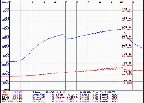
The vertical grey line is the reference line of the loggers
figures shown in the bottom data bar.
-
' Efficiency' is calculated with the
following formula =
Turbo Outlet -
Manifold Inlet
Turbo Outlet - Ambient Temp.
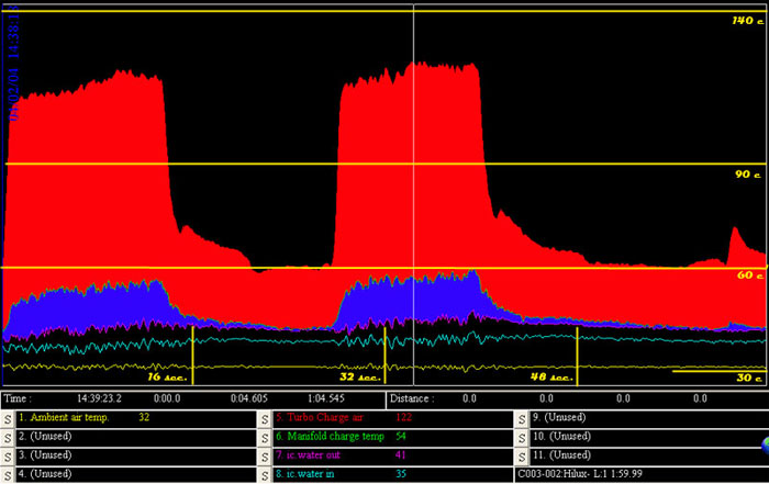
Customers cars Logs for comparison.
 |
 |
 |
 |
|
# Tony's
TD5 Defender. Just been chipped by MR Autos.,
otherwise as oe. Fifth gear was reached up the 1st
hill & 4th on the return-shown as spikes. Please
note this is oe. front mount air-air
intercooling, shown for comparison. More
efficient at speed only.
#
please read note
below |
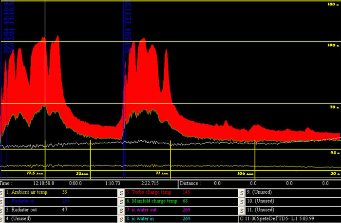
Tony
Patrol 3.0L let us log his car with a leaking oe top
mount intercooler. It allows us too show what a
pressure drop will do.
Click here to see full details. 137ºc out of
turbo, 85ºc into the engine on a 32ºc day, worst
scenario. |
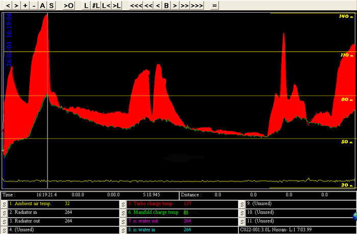
This is same car after we fitted our new upgrade
73mm core. No
leaks. 119ºc out of turbo, 68ºc into engine on a
30ºc day, worse case again - a bit more efficient,
but much more consistent cooling. Note also how
turbo temp dropped. Factory top
mounts are inefficient - some are shockers ! |
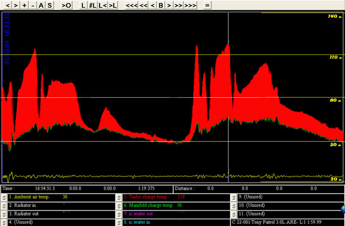
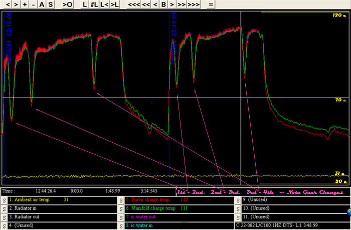
This is
Toy. L. Cruiser 100 series which has been fitted
with a non intercooled DTS kit. We are fitting our
air/water ic kit very soon. This vehicle carries
allot of weight. The turbo seems very efficient with
only 112ºc under a period of full load, on a 32ºc |
| oe IC.
efficiency = 71.8% |
oe IC.
efficiency = 49.5% |
are IC.
efficiency = 57.3% |
pipe.
efficiency = 1.2% |
| #
This is the factory front
mount intercooler, vehicle been chipped & tuned for
Australian conditions which helps a little with
cooler temps., & the 71.8% efficiency is why we do
not do any upgrades for this vehicle - a smallish
gain will be expensive. |
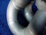
Our Air-Water Tube
Development story
This new tube
extrusion is the result of five years of research &
development carried out on our Air / Water intercoolers. The
first cores used modified intercooler tubes, but flowed too much
water for the charge air flow. For the second series we used
modified water cores, but these were the exact opposite, with
very high volume & pressure, pumps needed to achieve efficiency.
The most efficient a/w intercoolers we had made were with the
K&J oil cooler tubes, but water flow was still sensitive & the
tube area too large in relation to the fin area. Over these four
years, I was extremely lucky to have the input of an Engineer
who was contracted to the Australian engineering arm of
Caterpillar, in both Load Stress & Hydraulic Design. Soooo
(?), what's much more important is that Danny is a 'petrol head
enthusiast' who already knew the advantages of air/water
intercooling & so helped me with great enthusiasm with his deep
insight ! The ARE Sizing Spreadsheets were originally created (&
are still being fine tuned) by Danny with some input from me, to
short cut development time & create a superior product. Now, I
find that they keep me focused on the strength & weaknesses of
this system & really do make sure we can supply the very best
product
possible. Our design criteria was maximum heat transfer with
minimum pressure drop. Juggling the smallest tube volume (for
fluid speed) to the largest internal surface area ( for wall
contact) ratio parameters, is the secret.
Last year
when I first discussed with the Engineers @ Adrad where we were
at with our new extruded tube design & needing a factory too
manufacture the cores, it very quickly became apparent that the
costs were out of ARE's reach - or maybe I wasn't prepared to go
that far into debt! It now became a joint effort, with Adrad
both bankrolling & manufacturing the cores with our tube design.
They went to their supplier, Capral, to make the die & supply
extrusions. Not good. We were seriously messed with in the die
manufacture. Three separate times we had to make changes to the
design to enable the die to be made, being agonizingly slow
getting back to Adrad. Each time the Adrad drawing dept. had to
draw up one or several alternatives which ARE then ran through
our own computer spreadsheet programme, coming up with the most
efficient alternative. When we thought we had it right, Capral
said that they still couldn't make the die & wanted more
changes. Up until now we had been able to computer model the
changes for minimal losses, but now we were looking down the
barrel of some real compromises. During discussions, Capral
tried to outsource the die manufacture overseas, with a company
in Germany that they use, saying they can make the it. However,
one very small change had to be made, or the cost was many
thousands of dollars extra . Computer modelling showed that it
was a small sacrifice, nowhere near justifying the cost.
My point? This is a very complicated & the best possible tube &
fin design that is realistically available in the market place
today, & hopefully for a fair while time to come.
One of our real
advantages is complete versatility. We can have cores
manufactured for us with any intake window width of 100mm to
1200mm with a height of 50mm to 1200mm in tube multiples of 11
or 12mm. Core depth starting at 37mm & going through to a length
of - well 10 or more metres if the application
demanded & the customer could afford it. Fin pitch can be
anything from 5 fpi to 20 fpi. or in a fluid to fluid cooling
situation, no fins at all. Get the picture, we can cool an
engine - maybe I should say machine - from a 6kw, 50cc -
to a 10,000 kw. plus, 30 litre plus whatever, under the right
circumstances. Please don't Email me & waste both our times with
ridicules scenerios, I'm trying too show how versatile our
product can be - we are into performance automotive applications
- & obviously applications are limited by charge temperature -
400 deg. c., charge speed, sheer size &/or weight, cooling fluid
volumes & reserves, & at least 100 other parameters.
Heath Lawson - GU
4.2L td Patrol
t
|
07/03 Heath
does some heavy duty 4x4 competition & came to us to
see if we could drop his inlet temps down as he was
looking for more power & was concerned about his
inlet temps at full throttle/low range, even with an
aftermarket top mount air-air fitted.
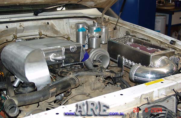
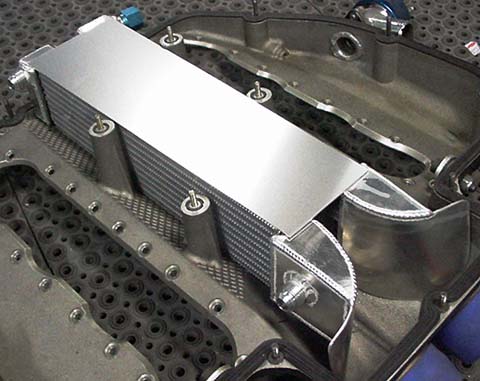
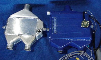
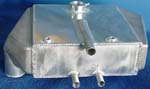
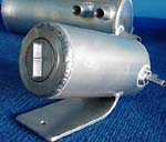
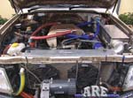
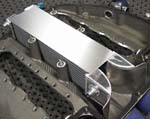
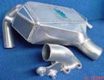
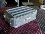
This is the top of the
air water we built for him
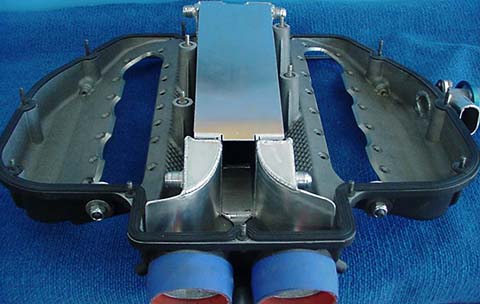
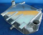
This is the bottom of
the unit. Note that we fitted 8 npt bosses for
temperature sensors - we like to see our products
being comprehensively tested. We used 2 of our Hot
Chilli tanks for the charge air. This unit was made
before we received our new tube, so we could now
build an even more efficient unit !
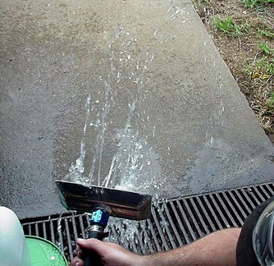
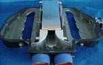
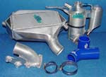
These are the
recovery (foreground) & distribution tanks we made.
These add nothing to the actual cooling rate, but
are to make sure that the system is always
completely full (check
this) compared to (this)
& there is enough water capacity in the system. If
there is not enough water capacity, a steam pocket
will develop in the 'cooler & it's useless !
Remember the charge air is always over 100ºc under
high load, so it will boil the coolant.
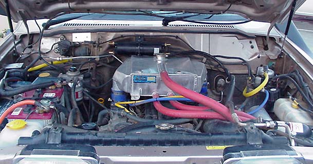
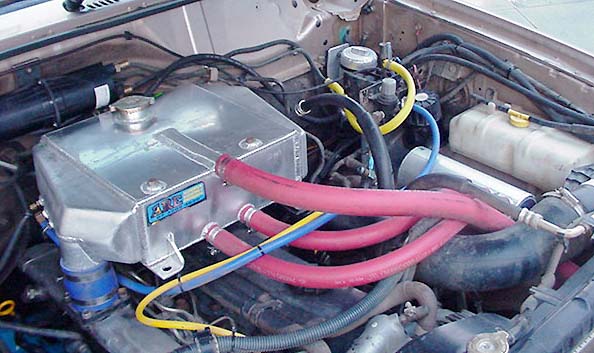
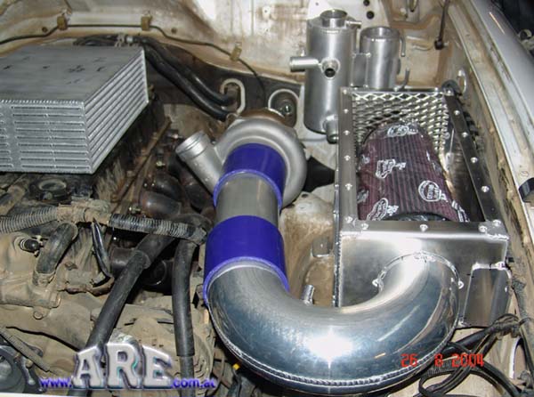
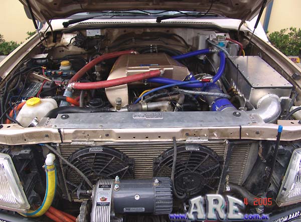
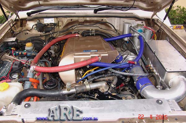
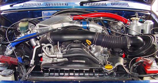
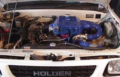
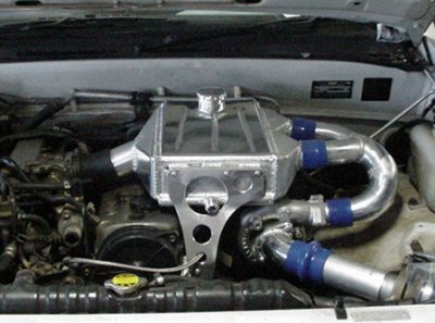
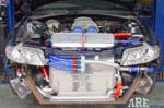
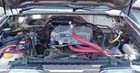
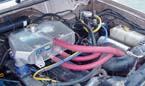
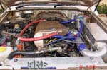
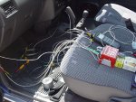
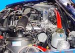
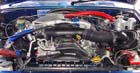
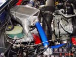
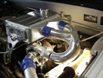
Under bonnet pics. of
the system fitted. No, the hose sizes aren't
overkill. We have developed a computer programme
over the last three years that gives us just about
complete data for this system before we start
fabricating - & we're backing up the theory with
practical data logging - most of the time -
occasionally there's a hic up.
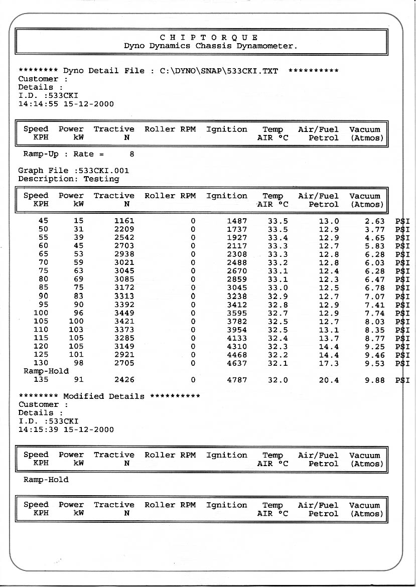
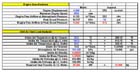
This is the
6
page PDF file from ARE's own computer programme for
sizing inter -coolers. Note on the first page that
our intercooler removes 25.2kw of heat out of the
charge air. A small household air conditioner is
approx. 1.6kw & a unit to do a lounge, dining &
kitchen is 8kw - so our little intercooler really
does do a big job, & this is why we put so much
effort into them. There is allot of hidden
information still!
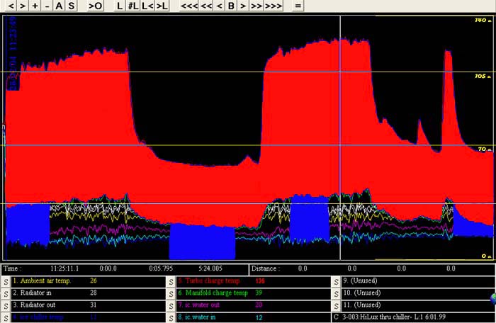
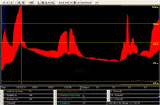
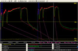
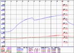
This is a log from
our first Datalogger. The red vertical line (@ 10
secs.) is the reference point for the temp figures
below. The Ambient temp. was not logged, but was
26ºc. The charge air temp. out of the turbo is 138ºc
with the temp out of the intercooler being 52ºc. The
39ºc is a spot under the bonnet that we wanted to
log for future reference. Intercooler
efficiency is 76.8% & resulted in the power gain on
the chart below.
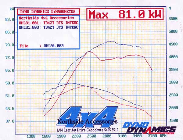
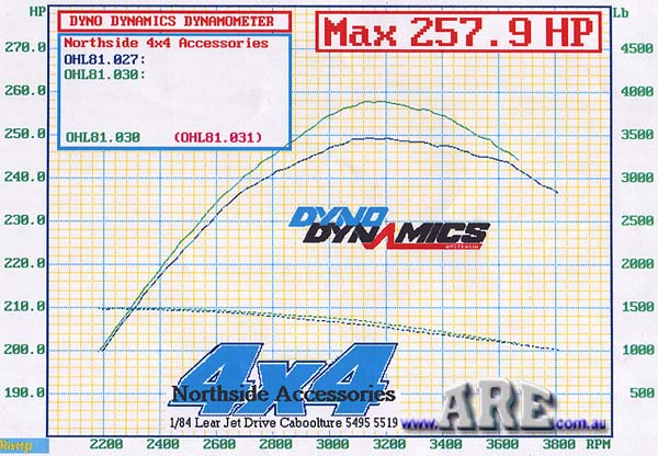
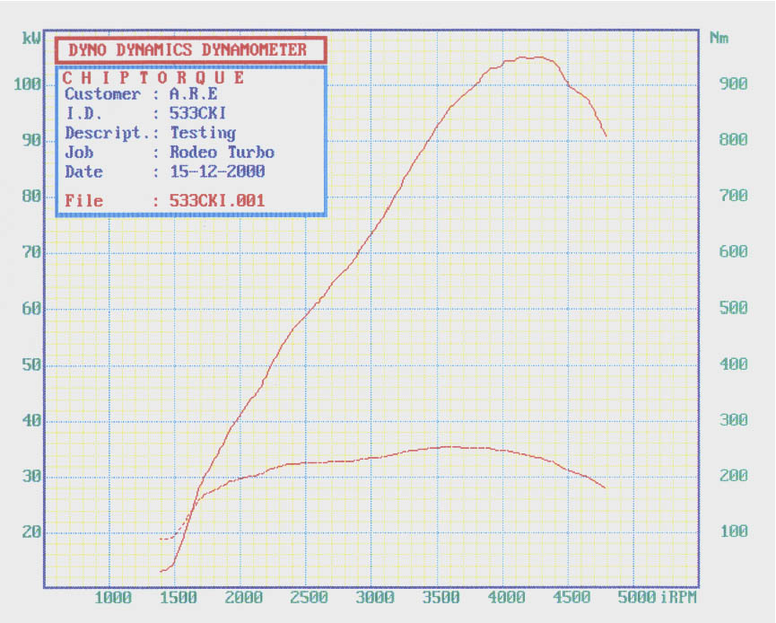
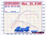
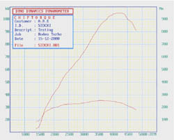
This is his dyno
sheet from Northside 4x4 (07- 5495 5549) of before &
after. It's also a perfect example of why I don't
take much notice of these dyno graphs - unless they
are accompanied by what I call the 'boiler room' -
the two sheets shown below. Notice how at 2450 rpm
the two lines meet with a big spike in the before
graph. Wonder why? without the boiler room sheet,
we'd never know, but we only have a look at the two
sheets too see why. 81.0kw is 108.6hp.
These figures are at the rear wheels with 36" mud
tyres, so the flywheel output rating is allot higher
- know I'm not conversant with the conversion
formula.
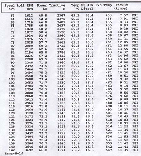
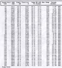
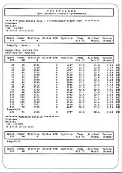
In this 'before'
graph, the boost starts jumping from 9.4lb @ 1800rpm
up to16lb @ 2340 rpm & then back to 9.5lb @ 2550rpm
slowly rising to 11.3lb @ 3600rpm. I
don't know what caused this spike, but the afr. (air
fuel ratio) & ex. temps didn't mind much so it
wouldn't do any damage to the engine.
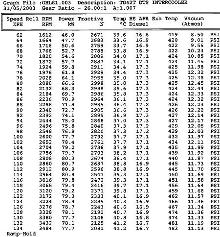
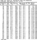
Now in
this 'after' graph, boost is 10.6lb @ 1800rpm
& stays around 12.4lb, thru to 2500rpm & then slowly
tapers down to 11.2lb @ 3500. It is so much more
stable & on average, apart from the spike, abit over
1 lb higher due to less pressure drop in our core.
The exhaust temps. are also much lower but it was a
little cooler day. A cooler
intake charge will give a little cooler
exhaust gas temps.
At 1700rpm our a-w intercoolers output went from 43
up to 51rwkw., or a gain of 8kw more. This
18.6% increase over top mount, & looks
after the engine better too boot !
At 2850 rpm our rwkw output went from 71kw up to
82rwkw, or an increase of 12. This is a
15.5% increase over top mount. Not bad
for replacing a competitors air - air intercooler
with one of ARE's air-water units. The
increase out in the bush or sand, will actually be
more, because the dyno fan blows heaps more air over
the bonnet than at 10 kph vehicle speed, BUT at this
speed our front radiator will be getting added air
flow from the engine fan, and water can hold heat 36
times better than air.
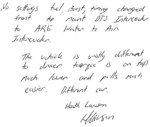
This is Heaths
signed vindication of the gain from fitting our
intercooler over the aftermarket one he already had.
Gains from 25% up, are seen with intercooling a non
intercooled turbo diesel. Be very wary of the
boost you run if you turbo a naturally aspirated
diesel & don't intercool it ! |
Update on Heaths diesel Patrol. -- 258rwhp.-
(198kw)
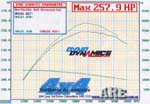 This
is 193kw @ rear
36" tyres! Wow ! This
is 193kw @ rear
36" tyres! Wow !

 |
This dyno graph is from the May
Labour Day competition @ the 3 day Landcruiser Park
bash. If this hasn't caught
your attention, then you must be a petrol head with
no knowledge of diesel engines. To put it into
perspective, with the same big chunky 36" tyres &
the same diff., he has gone from 75.3kw. with the
top mount air-air, to 81.0kw ( 7.6%increase) with
our air-water, to 193kw (138%increase) with our
prototype air-water intercooler-plennum unit !!!
Obviously, there is allot more than our intercooler
involved here. He went to a tubular exhaust, ball
bearing Garrett turbo, tidied inlet ports & a very
special big $$$ fuel pump. All the work was
performed by Heath & Ian with product from
businesses in south east Qld.
These three pics are what I used
to convince the guys to go with an untried idea I've
had for years, & spend much more than they wanted
too. I had shown them the six pages of our computer
modelling programme with a few different scenarios,
& they knew that was very accurate from past
experience, BUT, there was two stumbling blocks. The
plennum was untried & I'm not that big into diesels
so didn't give any guarantees, & Ian said that he
could do a Chev V8 conversion for similar money -
valid. Heath pointed out that while a V8 could have
more power, it would never have the low end Grunt &
engine breaking of these diesels. I'd given them a
bloody good price as they were the 'guinea pigs',&
it would be two at the same time, so it was crunch
time. I clearly remember the guys talking it over
out at their car for over an hour, before coming in
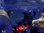
& laying a deposit down.
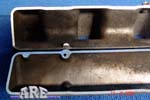
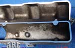
The carbon build up is a give away to the poor
factory design when the boost is raised. The blacker
the area, the slower the air speed &/or turbulence,
meaning those cylinders are not getting the same
amount of air. Three & four are clearly the lean
cylinders & will burn the pistons up early (or at
least dramatically shorten head gasket - valve -
ring life at best) at the tune levels these guys
wanted to go to. We also considered welding the
single entrie & making two entries into the oe log,
which would've been heaps cheaper, but I bet they're
bloody glad we didn't take that shortcut.
It's not the sort of job you get a
mate to do for a couple cartons. There's my thirty
years of air flow bench & 20 years of TIG welding
experience in this. I had to pad weld this part of
the inlet to get a very smooth transition with the
best transition angles. In fact, I picked up a
little flow on the second plennum, so cut the first
one off & did the same mod to it, at no charge. Not
many shops are that conciencious - or maybe I'm a
dickhead?
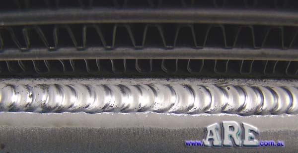
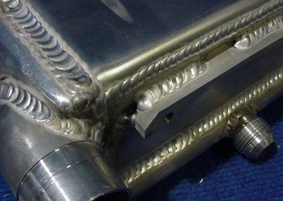
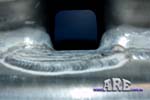
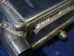
This is tricky welding, 3mm plate
butted onto 4mm plate of cladded alloy, 4 mm from
0.03mm fins & it has to be a full penetration
weld as it has the full weight of the cooling matrix
hanging off it.
Trial fit up during fabrication to
make sure everything lined up. The engine is
swallowing over 900 cfm now, & with the chunky tyres
throwing rocks, dirt & dust everywhere, filtering is
paramount. I just can't stress this enough. That's
why we fitted such a big K&N pod filter & our own
easily replaceable foam pre filter that slides in
the mesh near the entry.In a sense the inlet track
is 20mm long as that's the total of length between
the turbo outlet & tank inlet. How much lag?
Compared to a front mount it's almost unmeasurable.
Even though our plennum is 478% larger than oe., lag
is heaps less than a front mount instal
850rpm,
2500rpm,
4500rpm
- front mount & pipeing -
0.691 sec
0.235sec
0.131sec
- our air water/plennum assy.-
0.499 sec 0.169
sec
0.094sec
the above figures are from are computer modelling
Lag programme. They are how long it takes a molecule
of charge air to travel from the compressor housing
outlet to the valve head, at the rev. stated & if
the pipes are straight. There are far too many
variables to be able to calculate accelerating lag
as you can see it is exponentially quicker as revs
rise.
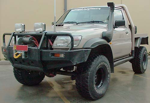
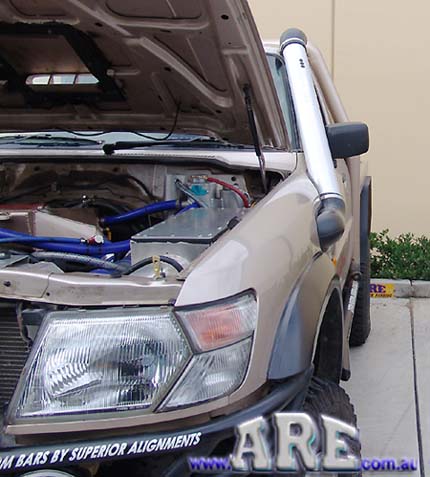
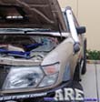
This is the end result on Heaths
truck. He kept the same radiator( which will
struggle on a long straight on a hot day), & of
course, the Davies Craig EWP will handle the flow
easily.
Apart from cost, the only other problem could be
longetivity, with so much weight swinging off the
top of a vibrating engine & then being pounded be
such rough use these guys throw their trucks at! We
have done everything possible with both materials
used & fabrication skill & tricks for the longest
life possible. The air speed in the short 63mm pipe
connecting the compressor housing to the the ic.
inlet tank is 254kph! We're now pulling 63kw (3583
BTU/m)of heat out of the intake charge, allowing
their other engine mods. to achieve the impressive
power output. They're good turbo petrol engine
specifications, but then I'd love to see this engine
in a 1400 kg VL Commodore beside allot of imports at
the lights! It would have similar power to a HSV 300
kw Monaro, less weight, & don't even think of how
much more torque !! What a burn out weapon - mega
grunt at any revs.
The air speed in the 4" snorkel is
92kph! so you can see why I talked them into such an
elaborate air box - it's necessary at this level
believe me. |
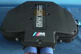
Rod Brennen - BMW
M5 Supercharged
This is a variation
of our usual air/water intercoolers
|

 |
So sad to see this
happen. Rod saw an air/water unit like this on a
USA. internet site, recognized straight away the
advantages for his new blower set up & sussed out
having it fabricated in Sydney. Weeeeeeeeeell, the
results of what he was charged for are shown in the
top two pictures, beside the unit we fabricated for
him. The guy sounded totally confident & competent,
so Rod just went ahead & ordered it. The sad thing
is that the shop took money for this botch up, gave
it to him knowing it leaked. When it's a tricky job,
if you haven't seen someone's work, make sure you do
before committing your money!
It almost looks like
they ladelled the alloy filler on, like a person who
can't solder! One of the worst "professional" jobs
I've ever seen, & it's not as though it's for a low
dollar car either.
The air/water unit we
made was 66mm longer & 8 rows of tubes high instead
of 6 rows, giving 48% more cooling area straight
off. Plus we shaped the inlet to trap 90% of the
charge air instead of approx. 50% of the other.
There is a surprising amount of cooling on offer
here because of the surface area provided by the two
core matrix. Because of the tube length, a fair
water speed through the core is needed. If this was
a tougher engine combo, then we would've routed the
water differently through the cores, approx. 20%
more cooling is available, but because the engine is
a sensible street combo, this unit will remove most
of the heat out of the charge air anyway, so a waste
of our time & his money.
ARE's in house
computer programme gives us the volume & speed of
the charge air, the heat kw. that needs to be pulled
out of this air, how long it's in the core for (only
milliseconds in this case), speed of the water
through the core, how long it's in the core & how
many Kw's heat the water can transport out. Then
it's a matter of adjusting the water flow, sizing &
configuring the front radiator, sizing the hoses (
that's another programme we have developed) & it
will work pretty bloody good!Actually we're not that
smart - as of the end of '03 our programme has an
accuracy of +/- 6% for most calculations, up to
+/-15% for some & total accuracy for some. By the
end of '04 I want these figures @ 3% & 10%.
The finished unit in
it's place in the air box. |
We built a number of intercoolers like this with modified
radiator cores & while they worked good, found that the water
tubes were too small in relation to the charge air passages.
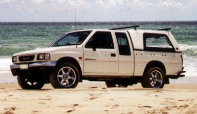
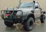
I really
like owning /doing something that's different to normal,
definitely not because I'm extrovert (I'm actually shy
in a crowd) but because of the challenge & satisfaction
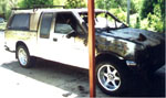
usually associated with the end result. Buying this
truck to replace my Rodeo was the result of a chance
remark during a conversation on another topic. From when
I first heard about it to ownership was only 3 days,
helped of course by the payout chque on my burnt truck,
so it looks like good can come out of bad.
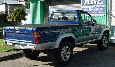
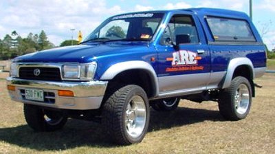
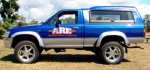
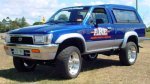
Richard
Larson of Loadsafe Australia (who incidentally are a
company qualified to engineer vehicle modifications
-(07) 3851 1066), bought a body damaged '95 Toyota Surf
3.0 litre automatic through Eureka Trading (07) 3865
1205, & then a 95 HiLux single cabin together with a '95
HiLux extra cab style side back. By welding the
appropriate mounts onto the chassis for the tray, the
vehicle pictured above is the result. Looks different?
The Surf, apart from having a coil sprung rear end, is
shorter in the wheelbase by the same length the extra
cab cabin takes up, what a lucky coincidence. It should
ride really nice when I get rid of the stiff coils &
shocks some Japanese guy had fitted, must've been trying
to get it to handle like a sports car!
Vehicle
Specifications
1995 Toyota
surf chassis with 1995 single cab body & extra cab tray.
AU Falcon blue & Pearl Silver.
Engine is a
1KZ-TE 3.0 litre 4 cyl. turbo diesel -non intercooled -
electronic controlled injection.
Transmittion
is 4 speed Automatic with rear LSD & electronic locking
front hubs.
Wheels &
Tyres are 16' x 7'' alloy with 265/75 x 16 Dunlop
tyres.
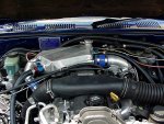
So Far
I've
added a vacuum/boost gauge to read off the intake
manifold & a probe in the inlet pipe out of the turbo to
give me the inlet charge temp. The boost max's. just
under 11 lb (10.8 lb) & is a little slow to come on,
especially from a standing start. A high stall converter
would help that initial jump off the line, can you
imagine ringing up the Converter Shop & ordering a high
stall, like all of 1200 RPM., Jeff would probably hang
up! Once a couple of meters have been traveled,
acceleration is surprisingly brisk - for a diesel,
remember the ute is lighter than a surf waggon. The
temp. gauge mirrors the boost gauge in that more boost
used, the higher the temp. Normal cruising throttle is
approx. 3lb. boost @ 66ºc.
Full throttle up hill is 11.4 lb @ 102ºc.
106.8ºc
is the hottest I have seen, that was yesterday morning
with most of our trade display in the back. This turbo
is nowhere near as efficient as the ball bearing Garrett
fitted to the Rodeo, as @ 10lb boost, 78ºc
was the hottest I ever saw. The other temp of concern is
average 50ºc.
min. sitting idling at traffic lights, - heat soak?
Plan of
Attack
First on the
agenda is to see what can be done with the computer. Not
too many mods. will be if the mixtures cannot be altered
as needed. Next of course, will be adapting the 4
intercoolers already made, to suit this engine, then
onto the Dyno. for power readings & temperature drops.
After this, it's unchartered waters as I know my way
around Hotrodding petrol engines but buggerall of
diesels. Present thoughts are tubular exhaust manifold &
hopefully a ball bearing turbo with a big exhaust to the
rear, 20psi boost, flow the head & tidy up what's
needed, a very small cam grind, an adjustable cam gear,
new intake with plennum chamber & still retain the
throttle body. These will be done as time & resources
allow, but my aim is 150 - 160 kw at the flywheel ! I
would love to hear from anyone who can give me solid
information/leads on reworking high speed diesels for
more power.
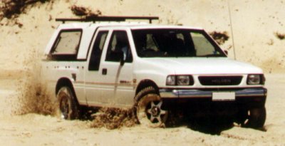
20 / 05 /
01
Up the
beach today revealed how much the load on an engine can
vary, I found a natural dyno for 4WD vehicles.
Travelling up in the soft sand in high range loaded the
engine to the tune of 11.7lb boost @ an immediate temp.
of 136ºc
& after a second so, 138 .4 degrees C. was the
temperature of the intake charge. Ambient temperature
was 25.3 degrees. I imagine this will be a similar temp.
to what I will see on the dyno., so there will be some
kw. to pick up here with our air/water intercoolers.
24 / 05 /
00
Bought a
pair of new tyres (one burnt, one singed) & then fitted
the 18' x 9.5" Enkie rims with 285/50 x 18 Pirelli
Scorpion Zero tyres off the Rodeo, onto the HiLux. A
very noticeable difference in the handling sharpness,
wet traction & ride, with all being much better. These
tyres are brilliant in all aspects except cost & beach
driving, as they don't bag as much as a high profile
tyre, guessing at having 10% less drive in soft sand -
most noticeable when accelerating from a standstill (60%
less - it feels like water skiing, a hell of a drag
until it pops up onto the top of the sand). One
important thing is that they are load weight & speed
legal, whereas high performance car tyres are not load
weight legal, this also applies to mini trucks, which
can now run legal big diameter low profile rubber for
the first time!
During
2001
We have been
so busy I haven't had the time to update this, but let
me tell you, it is one nice 4x4 to drive now!
How good is it, well
 That's
16.82 secs @ 135.2 kph That's
16.82 secs @ 135.2 kph
 on
our GTek meter recorded 02/01. It was run on the
same quarter mile piece of road I always use & back up
the fact that it embarrasses allot of cars off the
lights. Very satisfying too shut down a 'rice' car,
usually when the young guys just look in disbelief &
shake their head. It is just so quick in the first 100
meters, as long as it doesn't turn the tyres too much.
Of course, I'd never street race (for more than 200 m
anyway), so the real pleasure is fully laden with
camping gear going up the beach in the soft sand, or up
a steep hill - yes ! on
our GTek meter recorded 02/01. It was run on the
same quarter mile piece of road I always use & back up
the fact that it embarrasses allot of cars off the
lights. Very satisfying too shut down a 'rice' car,
usually when the young guys just look in disbelief &
shake their head. It is just so quick in the first 100
meters, as long as it doesn't turn the tyres too much.
Of course, I'd never street race (for more than 200 m
anyway), so the real pleasure is fully laden with
camping gear going up the beach in the soft sand, or up
a steep hill - yes !
January
2004
I've been
very happy with the truck & it's performance to the
point of being so busy, not worrying about any more
modifications. Now, with our new air/water tube
extrusion, I will data log the current unit again, &
then build a new 'cooler & data log it's results.
February 2004 Our NEW HI LUX KIT -
final testing
| |
 |
 |
 |
|
This is the 2 row radiator & DC. EWP. we
supply in our kit. ' pic up
soon. ' |
This is our header tank -recovery tank assy.
needed for water capacity. |
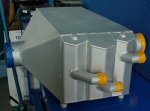
This is the intercooler assembly with the
plennum adapter in the foreground. |
This is the kit of our product Water pump,
radiator and hoses are not shown. |
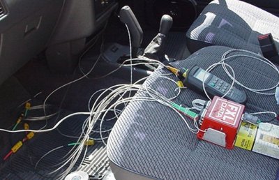
These are
the pictures of our new air/water intercooler that is
now available as a kit for the late '90 1KZ-TE 3.0L. The
new data log graphs are shown further back this page.
Note the number of test leads for our data logger. We
really do get a complete picture of exactly how every
thing works so we can improve any weaknesses.
We have not
been back on the dyno yet & it is not a priority as the
purpose of our new intercooler tube was a little better
performance over our last version - which really gave a
big power increase, BUT mostly - STRENGTH. It was
very concerning to have a 0.3mm (0.012") tube with water
on one wall & charge air on the other. If they ever met,
trouble, as into the engine it goes! Our new tube is
1.1mm (0.044") wall giving 3.7 times more
strength.
|

Started in 2000
We built
a number of intercoolers like this with modified
intercooler cores & while they worked good, found that
the water tubes were too large in relation to the charge
air passages.
Project
Rodeo is no longer...
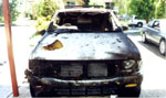
Due to a
serious house fire in mid March, I have lost my
wheels & test bench in 20 mins. of hell. Good has
come out of the bad & even though I'm down heaps of
insurance, I've been lucky enough to pick up a truck
that may prove to be an even better set of wheels.
Project HI LUX/SURF !
What
happens when you work on customer's hot streeters
everyday? You build your own...
Ingredients:
Result:
-
A 1992
Holden Rodeo, 2.6 liter standard engine, with a
330hp rated Garrett GT25 ball bearing turbo
(supplied by John Patrick @ Turbo Supplies,
Townsville (07) 4721 5133), and a custom air to
water intercooler.
The
Background
When my wife
and daughter dragged me camping 'up the beach' with them
in their '89 Suzuki Vitara earlier this year, I found it
to be the only way in the last 3 years that I stopped
thinking/working ARE. So, I wanted to come up with
a 4wd that had enough room, to use for camping, and for
work........
The Idea
My wife drives her XG falcon Ute for
pickup/deliveries, which she didn't want sign written,
so I'll give her my Mazda MX6 & buy an early '90's
4wd like a Courier, Triton, or Rodeo, stick a turbo and
intercooler on it, add mags, tires and sign
writing, & then watch the sand fly!!!
The
Result
Mathew at Chiptourque told me that a Rodeo up to mid
92 (I found out 10/92) has room in the computer to burn
a program for boost, hence the cost of an aftermarket
computer is avoided. I might add that he runs this
computer in his 10 sec. / 124 mph. Rodeo engined street
Gemini. I spotted a '92 Rodeo Spacecab advertised in the
Trading Post. After checking it out we purchased
it for just under 12 grand.
The
Intercooler
In my
opinion, too many people dismiss an air/water
intercooler without serious thought to if it would suit
their application better than an air/air unit. I think
two of the best uses are for four wheel drives &
especially drag cars or dyno shootout cars. Below is my
"maximum attack" setup which has involved allot of R&D
time, especially in water flow through the 'cooler &
design of the "ice box". I have installed 14 pressure &
temperature sensors to monitor exactly what happens &
help develop this into an ultimate setup. I already have
2 ideas which should improve the results on
big kw. engines, but some baseline results are needed
first. Below ambient temperatures is the goal, & that
sure as hell is what I'd rather have into my combustion
chamber, than the guy in the lane beside me, or next up
on the rollers. Please note that the last sentence does
not apply to a four wheel drive, but the compactness,
lack of piping to the front of the truck & lack of turbo
lag (especially diesel), sure as hell does.
 |
 |
 |
|
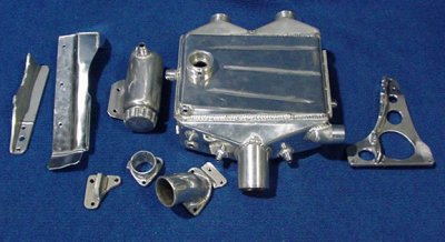
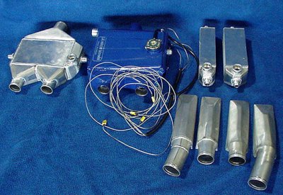
The Components -
what it takes to make an air to water
'cooler? NB. radiator, ice box & pump not
shown |
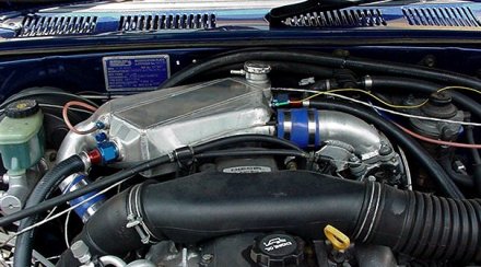
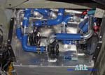
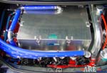
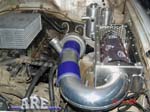
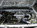
The engine bay -
intercooler and all. No turbo lag here !! |
The ARE custom
air to water intercooler. Sure going to need
HPC on the exhaust here! |
|
 |
 |
 |
|
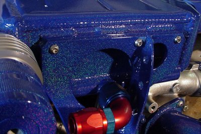
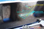
A close up of
the front mount of the intercooler,
check out the HPC coating colour and the
speedflow fittings. |
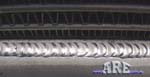
Whether it be a
customer's car or our own shop vehicle, we
take pride in our work, especially our
welding & R&D. |
Prototype "ice
box" nearing completion. This should give
seriously cool water to the intercooler |
|
|
|
|
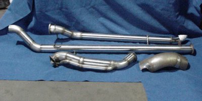
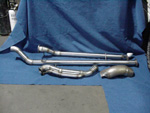
The
Exhaust
We custom
fabricate intercooling piping, why not create a custom
exhaust? This is the first & last time, back to
Gonzo or Custom Exhaust in the future. Don't even think
of asking, this is not my field.
The
extractors we made ,keep the turbo up out of moisture
 |
 |
 |
 |
|
The extractors
we made ,keep the turbo up out of moisture
|
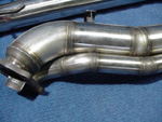
Dump pipe with
separate wastegate pipe. |
Wastegate pipe
is aimed into the low pressure area of the
bend. Shield at bottom right is to keep heat
off intercooler. |
Close up of
welding on pipes
|
The Results
Drove the truck for the
first time this week, without water in the 'cooler, only
a short run. Heat soak temperature in the intercooler &
piping after switch off was even more dramatic than
power gains. 3.5 - 4.0 lb boost was all the oe. computer
could handle, but it's booked in on Chiptorques rollers
15/12 to fix this problem. Third gear has 4lb boost @
2000 rpm & fifth gear has 3.5 lb. boost at 1600 rpm.
It's going to be a bloody "stump puller", all I hope is
that there is still sufficient boost at 5500 - 6000 rpm
redline. Thankfully I made the wastegate linkage
adjustable, as first real stab on the throttle resulted
in big rev, blurred needle to10lb. boost, & a near head
butt into steering wheel with "computer shutdown".
Back to workshop & it's now down to 6lb. max. Even at
3lb. boost the truck feels at least one gear better!
Only annoying problem is the engine will die quite often
at lights & the idle mixture is impossible to get
consistent.
26 / 12 / 00
It will be best to head
the updates with the date posted, this will make it
easier to follow. Below are two JPegs of scanned Dyno
results of my 15 / 12 / 00 date with Chiptorque. The man
himself, Lauchlan, conducted all the tuning runs & I
have to say I was most impressed with his thoughorness &
professionalism. Five problems that he predicted before,
reared there head during the session, although I also
knew three of them would happen, -run out of injectors,
-run out of air (air flow meter), -run out of fuel
(pump). I may be able to get away with the oe. pump, but
I'm upgrading it with the others to be safe, & also save
a possible third trip down the coast. The other two
things I overlooked were blow off valve venting to
atmosphere & tappet cover breather not connected to air
intake after air flow sensor. I vent the blow off valve
to atmosphere in my MX6 (rather my wife's now!) without
causing any problems & I hoped the Rodeo would be the
same, & I haven't received my air/oil separator,
intercooler recovery tank & Charcoal canister back from
HPC yet, so I didn't worry about connecting the hose.
Wrong on both counts, came home & plumbed both hoses
into intake & no more snuffing. It also muffled the blow
off noise, so I've gone from being a 17 year old hoon
back to a 50 year old petrolhead, god damn it !
The above graph on the
left is the standard graph printed in most magazine
articles, with one exception, - the bottom scale is revs
& not kph. I want to know what it's got at a certain
rev., as it applies then in every gear, saving having to
work out rpm/rev later on. This is good & easy to look
at & compare with others, but I call it the "cosmetic"
graph. To me, the real "mechanics" graph is the chart
shown on the right side above. This gives the real
GUTS of the engine performance! It shows a much,
much more complete look at the engines capabilities &
potential, & off course, it's limitations & weaknesses.
Unfortunately, neither graph tells you the gear used for
the power runs, which is important to know. All tests on
my truck were conducted in fourth gear with
285/50 x 18" tyres.
Before I started, the
Rodeo had 62kw. @ 5850rpm at the wheels in third
gear on Brisbane Tuning & Turbo dyno (it will go back on
theirs when it's finished, for an accurate before/after
comparison), fitted with extractors & sports exhaust.
Chiptorque did a Rodeo with extractors, sports exhaust &
camshaft, with a resulting 67 kw., so I'm ecstatic with
my 105 kw.@ 4133 rpm, because we were starting to
run out of fuel, meaning there's more left in the old
girl yet, hopefully 140kw, which will be a 233% increase
in power. Even that is not the most impressive feature
of the engine, & unfortunately, I can't show you without
taking you for a ride! The boost is instantaneous - as I
squeeze the throttle, the boost needle rises straight
away, I kid you not. This is due to the expert (or
lucky) matching of the turbo (remember it's a new age
hybrid Garret) by John at Turbo Supplies, the extractor
exhaust & the extremely short inlet track of the
air/water intercooler (check it out compared to yours)!
I reckon the engine is hyperactive down low & Lauchlan
said it was like an angry ant on the rollers. To give
you some idea the above is true & I'm not exaggerating,
look at the boost figures & then compare to your known
figures, like 2.63 lb of boost at 1487rpm & 5.83lb of
boost at 2117 rpm, it's like driving a V8 automatic, no
bugger it, it's better than driving a V8 automatic!
I didn't even bother to
put ice in the "box" & am know wondering if I will be
able to test it's capabilities at all. The hottest turbo
outlet temp. was 72 deg. C, the hottest inlet temp
was 40.8 deg., the hottest water outlet temp (of
the 'cooler) was 38.4 deg. with a 'cooler inlet temp. of
36.7 deg., meaning the biggest "working" temperature
difference in the intercooler was 2.4 deg. when it was
removing 31.2 deg out of the inlet temp., however,
remember that this is only at 9.53lb boost. This was
also with the water pump on half speed. In the soft
sand, the water temp. started to climb above these
figures, but switching the pump to full 13V dropped the
temps. straight away. Of interest, I often see the
'cooler inlet temps. up to 3 deg. (but mostly 1.5 to 2
deg.) higher than the outlet temps, when I stop, due to
under bonnet heat soak. I have a couple of ideas to cut
down on this & will try to implement them before I go
back on the dyno.
Nothing under the tappet
cover has been touched yet, so the engine is completely
stock. When I fit larger injectors, air flow meter (off
a 200SX incidentally) & fuel pump, I will then get
Lauchlan to tune it for 10lb boost first, & then add
some avgas (I run Optimax now) & hopefully I can run 15
lb boost when I want to. It will be interesting to see
how long the engine lasts at these levels, but remember
three things, -1st -the engine is a commercial design -
meaning they are usually beefier than passenger car,
-2nd- it has 8.3:1 compression std., & with my normal
driving, it's usually 4' - 10'' vacuum, with occasional
4 -7 lb boost showing, which means most of the time the
engine is under no more stress than std. However, as
soon as I come across another engine, I will be buying
it & fitting forged pistons & rods, gapless rings & a
very mild turbo cam, as I know the current engine, isn't
going to last forever!
More Testing
6 weeks up to 17 / 02 / 01
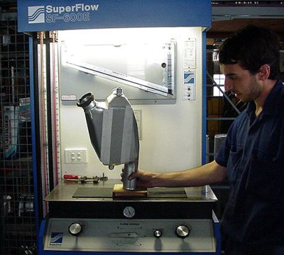
a) This is the
SuperFlow 600E flow bench of Bryant Engineering (07-3846
2674) -(who incidentally have done all my engine
machining for 33 yrs)- is the biggest model available.
When testing intercoolers we have to have all eight
motors switched on & the fine adjustment set on either 5
of 6, or 6 of 6 & if I'm testing tanks only & even with
60mm pipes, I have to read the manometer at less
than the 25" normally used & then convert. That will
give you some idea of the air flow available through
intercoolers, necessitating the use of a powerful
machine for accurate results if doing allot of
experimentation. I am lucky & privileged to have the use
of this bench, but it may also result from building a
friendship & loyal customer over a long period.
b) I try to perfect
everything we sell. This is the best of 3 designs of the
intercooler water inlet tank. A parallel tube with13
holes drilled to supply a uniform pattern of water
equally to all the tubes running through the core. This
eliminates "hot & cold spots" I find in other products,
which is important to pull as much heat out of the
intake charge as is possible.
c) The 4 intercoolers to
be tested on the dyno, the tanks have yet to be welded
onto the 2 cores, right hand side. Note the 4
temperature probes used on the original 'cooler made for
the Rodeo. I'm positive the 92.8 % smaller size 'cooler
on the left of the original will prove to be noticeably
more effective at cooling the intake charge! This is
even though it has better air flow by 10.2%!!! This is
because of the totally different core construction we
use in this new line of intercoolers, suitable only in
air/water applications though! The smallest core (on the
right of the blue 'cooler) is 479% smaller than the blue
'cooler & flowed 2.3% better. The core on the far right
is 322.5% smaller & flowed 1.1% worse than the blue
'cooler. Note that the larger core on the right had
better flowing "radiused" tanks, so would've flowed less
again if fitted with the same tanks by a
calculated3.1%. Also note that air flow through the core
is only part of the heat dissipation equation, if core
construction is the same, usually the better flowing
core will actually cool the intake charge less.
d) The core
construction of these two intercoolers differs
completely & will give the unusual result of the
intercooler on the left with 10.2% better flow, cooling
the intake charge better than the larger, less flowing
blue 'cooler on the right &, originally fitted to the
Rodeo. Note that the colour has nothing to do with
cooling efficiency, as it is all internal in an
air/water setup & blue is constantly mentioned only to
distinguish the original intercooler fitted for the
first dyno session. The less restriction will also
result in more kilowatts, giving a double bonus!
Three Days Before "THE
FIRE"
I got the Rodeo back on
the road with a new fuel rail we fabricated for the high
flow injectors from Ray Box of Petro-Ject (07) - 3857
8022. They are Bosch part no.
to suit Mitsubishi TR Magnas& flowed 28% more fuel than
rodeo oe. units. Even though they had a different
impedance rating, they worked well enough to drive
around on until I could get onto Chiptorques dyno - rich
in the mid range. The truck just kept pulling hard right
up to 6K a couple of times that I tried it, wish I
had've been able to let Lauchlan do the final dyno
session.We also fitted a extra heavy duty clutch built
up by Dennis at Direct Clutches (07) 3862 2680. He had a
steel flywheel turned up to suit a Mazda RX7 upgraded
pressure plate & an organic Rodeo clutch plate. a
good job but it took 3 weeks longer than I was told.
really had allot of "bite", but was still progressive
enough to be able to do a hill start without the
handbrake.
Of course this now
means that the day booked on the dyno was cancelled
along with being able to size the four intercoolers I
had made. These will now be tested on the HiLux,
hopefully by June.
|
Atlas Engineering - 16L, 28 psi. Mulcher. |
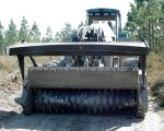 |
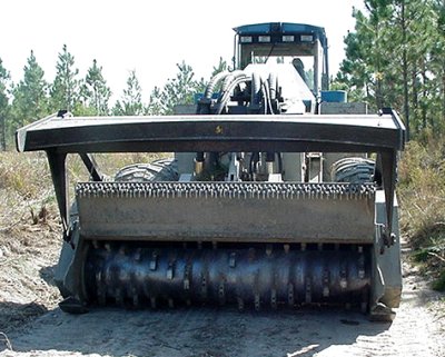
ATLAS
ENGINEERING'S prototype forest mulcher.
Cummins 16 litre, 6 cyl., 450hp.,28 psi. |
|

This is
an11kb PDF file. Worth
a look
 |
There is
a reason for the three pairs of tanks &
also for the different profiles of the
tanks. Yes !
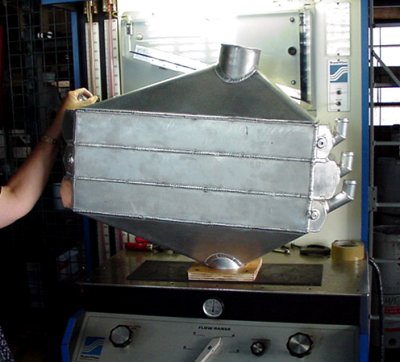
This is
one of a few intercoolers that totally
overtaxed Bryant Engineerings flow
bench. In fact it is only limited by the
102mm inlet/outlet pipes. This is part
of the reason I don't list cfm figures,
some that I read are a complete
fabrication & would make ours look bad,
they are so easy to manipulate & are
unsubstantiated. Yeh, it pisses me off,
buts that's business.
The
explanations & text for this file are @
Research & Development
where you can see that under certain
conditions we got better than 100%
efficiency compared too both/either the
inlet water temp. & the ambient temp. It
shows that if I showed you a particular
second snapshot we have these figures,
but not under normal operation,
although we are still around 98% to the
water temp. & 73% to ambient - let down
by the radiator.
|
|
 Check
back for updates.... Check
back for updates....
|
|